N-Tier cache redirection
To efficiently handle large amounts of cached data, typically several gigabytes per second, an Internet Service Provider (ISP) deploys several dedicated cache servers. The cache redirection feature of the Citrix ADC appliance can help load balance the cache servers, but a single appliance or a couple of appliances might not efficiently handle the large volume of traffic.
You can solve the problem by deploying the Citrix ADC appliances in two tiers (layers), where the appliances in the upper tier load balance those in the lower tier and the appliances in the lower tier load balance the cache servers. This arrangement is called n-tier cache redirection.
For purposes such as auditing and security, an ISP has to track client details such as the IP address, information provided, and the time of the interaction. Therefore, client connections through a Citrix ADC appliance have to be fully transparent. However, if you configure transparent cache redirection, with the Citrix ADC appliances deployed in parallel, the IP address of the client has to be shared among all the appliances. Sharing of the client IP address creates a conflict that makes network devices, such as routers, cache servers, origin servers, and other Citrix ADC appliances, unable to determine the appliance, and therefore the client, to which the response should be sent.
How N-tier cache redirection Is implemented
To solve the problem, appliance n-tier cache redirection splits the source port range among the appliances in the lower tier and includes the client IP address in the request sent to the cache servers. The upper-tier Citrix ADC appliances are configured to do sessionless load balancing in order to avoid unnecessary load on the appliances.
When the lower-tier Citrix ADC appliance communicates with a cache server, it uses a mapped IP address (MIP) to represent the source IP address. Therefore, the cache server can identify the appliance from which it received the request and send the response to the same appliance.
The lower-tier Citrix ADC appliance inserts the client IP address into the header of the request sent to the cache server. The client IP in the header helps the appliance to determine the client to which the packet should be forwarded when it receives the response from a cache server, or the origin server in case of a cache miss. The origin server determines the response to be sent according to the client IP inserted in the request header.
The origin server sends the response to an upper-tier appliance, including the source port number from which the origin server received the request. The entire source port range, 1024 to 65535, is distributed among the lower-tier Citrix ADC appliances. Each lower-tier appliance is exclusively assigned a group of addresses within the range. This allotment enables the upper-tier appliance to unambiguously identify the lower-tier Citrix ADC appliance that sent the request to the origin server. The upper-tier appliance can therefore forward the response to the correct lower-tier appliance.
The upper-tier Citrix ADC appliances are configured to do policy-based routing, and the routing policies are defined to determine the IP address of the destination appliance from the source port range.
Setup necessary for configuring N-Tier CRD
The following setup is necessary for the functioning of n-tier cache redirection:
For each upper-tier Citrix ADC appliance:
- Enable Layer 3 mode.
- Define policies for policy-based routes (PBRs) so that traffic is forwarded according to the range of the destination port.
- Configure a load balancing virtual server.
- Configure the virtual server to listen to all the traffic coming from the client. Set the Service Type/Protocol to be ANY and IP Address as asterisk (*).
- Enable sessionless load balancing with MAC-based redirection mode to avoid unnecessary load on the upper-tier Citrix ADC appliances.
- Make sure that the Use Proxy Port option is enabled.
- Create a service for each lower-tier appliance and bind all the services to the virtual server.
For each lower-tier Citrix ADC appliance,
- Configure the cache redirection port range on the appliance. Assign an exclusive range to each lower-tier appliance.
- Configure a load balancing virtual server and enable MAC-based redirection.
- Create a service for each cache server that is to be load balanced by this appliance. When creating the service, enable insertion of client IP in the header. Then, bind all the services to the load balancing virtual server.
- Configure a transparent mode cache redirection virtual server with the following settings:
- Enable the Origin USIP option.
- Add a source IP expression to include the client IP in the header.
- Enable the Use Port Range option.
How N-tier cache redirection works during a cache hit
The following figure shows how cache redirection works when a client request is cacheable and the response is sent from a cache server.
Figure 1. Cache Redirection in Case of a Cache Hit
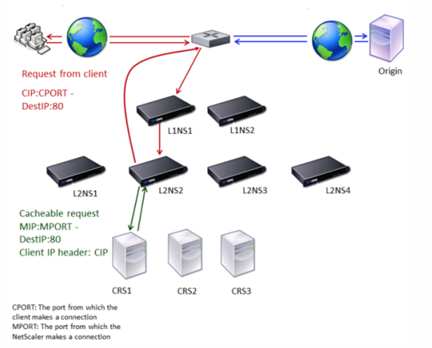
Two Citrix ADC appliances, L1NS1 and L1NS2, are deployed in the upper tier, and four Citrix ADC appliances, L2NS1, L2NS2, L2NS3, and L2NS4, are deployed in the lower tier. Client A sends a request, which is forwarded by the router. Cache servers CRS1, CRS2, and CRS3 service the cache requests. Origin Server O services the uncached requests.
Traffic flow
- Client sends a request, and the router forwards it to L1NS1.
- L1NS1 load balances the request to L2NS2.
- L2NS2 load balances the request to the cache server CRS1, and the request is cacheable. L2NS2 includes the client IP in the request header.
- CRS1 sends the response to L2NS2 because L2NS2 used its MIP as the source IP address when connecting to CRS1.
- With the help of the client IP address in the request header, L2NS2 identifies the client from which the request came. L2NS2 directly sends the response to the router, avoiding unnecessary load on the appliance in the upper tier.
- The router forwards the response to Client A.
How N-tier cache redirection works during a cache bypass
The following figure shows how cache redirection works when a client request is sent to an origin server for a response.
Figure 2. Cache Redirection in Case of a Cache Bypass
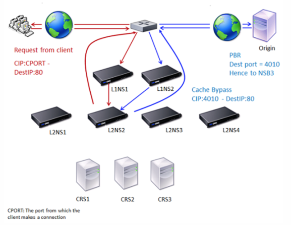
Two Citrix ADC appliances, L1NS1 and L1NS2, are deployed in the upper tier, and four Citrix ADC appliances, L2NS1, L2NS2, L2NS3, and L2NS4, are deployed in the lower tier. Client A sends a request, which is forwarded by the router. Cache servers CRS1, CRS2, and CRS3 service the cache requests. Origin Server O services the uncached requests.
Traffic flow
- Client sends a request, and the router forwards it to L1NS1.
- L1NS1 load balances the request to L2NS2.
- The request is uncacheable (cache bypass). Therefore, L2NS2 sends the request to the origin server through the router.
- The origin server sends the response to an upper-tier appliance, L1NS2.
- According to the PBR policies, L1NS2 forwards the traffic to the appropriate appliance in the lower tier, L2NS2.
- L2NS2 uses the client IP address in the request header to identify the client from which the request came and sends the response directly to the router, avoiding unnecessary load on the appliance in the upper tier.
- The router forwards the response to Client A.
How N-tier cache redirection works during a cache miss
The following figure shows how cache redirection works when a client request is not cached.
Figure 3. Cache Redirection in Case of a Cache Miss
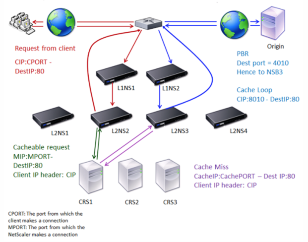
Two Citrix ADC appliances, L1NS1 and L1NS2, are deployed in the upper tier, and four Citrix ADC appliances, L2NS1, L2NS2, L2NS3, and L2NS4, are deployed in the lower tier. Client A sends a request, which is forwarded by the router. Cache servers CRS1, CRS2, and CRS3 service the cache requests. Origin Server O services the uncached requests.
Traffic flow
- Client sends a request, and the router forwards it to L1NS1.
- L1NS1 load balances the request to L2NS2.
- L2NS2 load balances the request to the cache server CRS1 because the request is cacheable.
- CRS1 does not have the response (cache miss). CRS1 forwards the request to the origin server through the appliance in the lower tier. L2NS3 intercepts the traffic.
- L2NS3 takes the client IP from the header and forwards the request to the origin server. The source port included in the packet is the L2NS3 port from which the request is sent to the origin server.
- The origin server sends the response to an upper-tier appliance, L1NS2.
- According to the PBR policies, L1NS2 forwards the traffic to the appropriate appliance in the lower tier, L2NS3.
- L2NS3 forwards the response to the router.
- The router forwards the response to Client A.