Scalability
Because TCP optimization is resource intensive, a single Citrix ADC appliance, even a high end –appliance, might not be able to sustain high Gi-LAN throughputs. To expand the capacity of your network, you can deploy Citrix ADC appliances in an N+1 cluster formation. In a cluster deployment, the Citrix ADC appliances work together as a single system image. The client traffic is distributed across the cluster nodes with the help of external switch device.
Topology
Figure 1 is an example of a cluster consisting of four T1300-40G nodes.
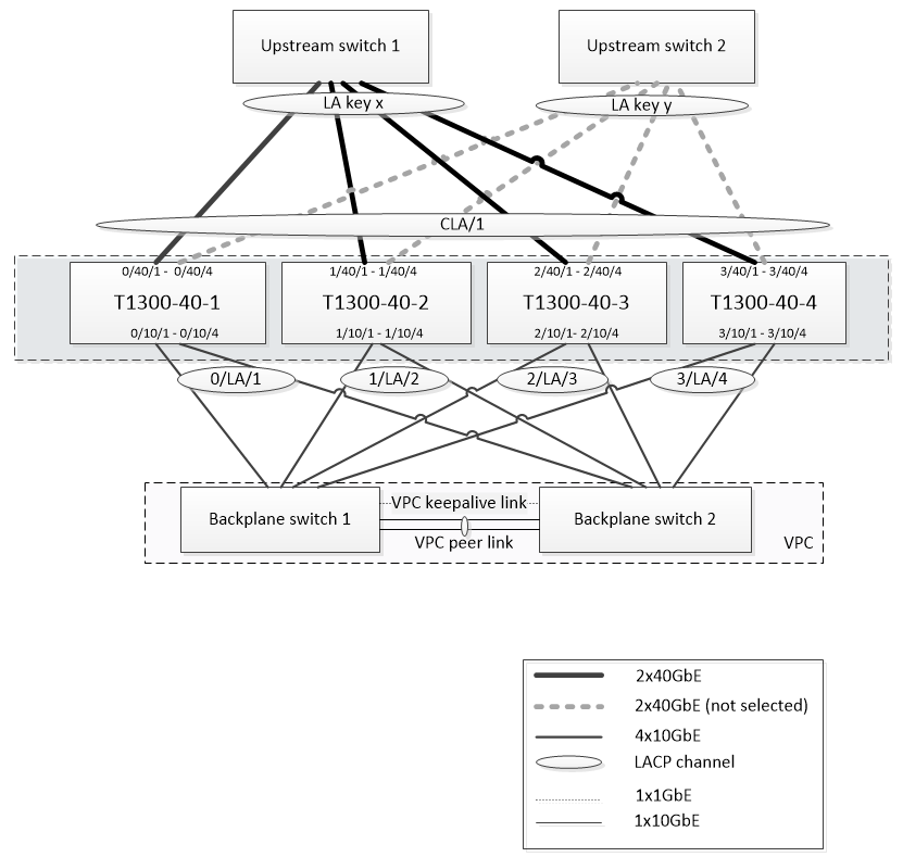
The setup shown in Figure 1 has the following properties:
- All cluster nodes belong to the same network (also known as an L2 cluster).
- Data plane and backplane traffic are handled by different switches.
- Assuming Gi-LAN throughput is 200 Gbps and that a T1300-40G appliance can sustain 80Gbps of throughput, we need three T1300-40G appliances. To provide redundancy in case of single cluster node failure, we deploy four appliances in total.
- Each node will receive up to 67Gbps of traffic (50Gbps in normal operating conditions and 67Gbps in case of single cluster node failure), so it needs 2x40Gbps connections to the upstream switch. To provide redundancy in case of switch failure, we deploy a couple of upstream switches and double the number of connections.
- Cluster Link Aggregation (CLAG) is used to distribute traffic across cluster nodes. A single CLAG handles both client and server traffic. Link Redundancy is enabled on the CLAG, so only one “subchannel” is selected at any given time and handles the traffic. If some link fails or throughput falls below specified threshold, the other subchannel is selected.
- The upstream switch performs symmetric port-channel load balancing (for example, source-dest-ip-only algorithm of Cisco IOS 7.0(8) N1(1)) so that forward and reverse traffic flows are handled by the same cluster node. This property is desirable because it eliminates packet reordering, which would degrade TCP performance.
- Fifty percent of data traffic is expected to be steered to backplane, which means each node will steer up to 34Gbps to other cluster nodes (25Gbps in normal operating conditions and 34Gbps in case of single cluster node failure). Thus, each node needs at least 4x10G connections to the backplane switch. To provide redundancy in case of switch failure, we deploy a couple of backplane switches and double the number of connections. Link redundancy is not currently supported for backplane, so Cisco VPC or equivalent technology is desired to achieve switch-level redundancy.
- MTU size of steered packets is 1578 bytes, so backplane switches must support an MTU more than 1500 bytes.
Note: The design depicted in Figure 1 is also applicable to T1120 and T1310 appliances. For T1310 we would use 40GbE interfaces for the backplane connections, since it lacks 10GbE ports.
Note: While this document uses Cisco VPC as an example, if working with non-Cisco switches alternate equivalent solutions could be used, such as Juniper’s MLAG.
Note: While other topologies such as ECMP instead of CLAG are possible, they are not currently supported for this particular use case.
Configuring TCP Optimization in a Citrix ADC T1000 Cluster
After physical installation, physical connectivity, software installation, and licensing are completed, you can proceed with the actual cluster configuration. The configurations described below apply to the cluster depicted in Figure 1.
Note: For more information about cluster configuration, see “Setting up a Citrix ADC cluster.”
Assume that the four T1300 nodes in Figure 1 have the following NSIP addresses:
Four T1300 nodes with NSIP address:
T1300-40-1: 10.102.29.60
T1300-40-2: 10.102.29.70
T1300-40-3: 10.102.29.80
T1300-40-4: 10.102.29.90
The cluster will be managed through the cluster IP (CLIP) address, which is assumed to be 10.78.16.61.
Setting Up the Cluster
To begin configuring the cluster shown in Figure 1, log on to the first appliance that you want to add to the cluster (for example, T1300-40-1) and do the following.
- At the command prompt, enter the following commands:
Command:
> add cluster instance 1
> add cluster node 0 10.102.29.60 -state ACTIVE
> add ns ip 10.102.29.61 255.255.255.255 -type clip
> enable cluster instance 1
> save ns config
> reboot –warm
2. After the appliance restarts, connect to the Cluster IP (CLIP) address and add the rest of the nodes to the cluster:
Command:
> add cluster node 1 10.102.29.70 -state ACTIVE
> add cluster node 2 10.102.29.80 -state ACTIVE
> add cluster node 3 10.102.29.90 –state ACTIVE
> save ns config
3. Connect to the NSIP address of each of the newly added nodes and join the cluster:
Command:
> join cluster -clip 10.102.29.61 -password nsroot
> save ns config
> reboot –warm
4. After the nodes restart, proceed with backplane configuration. On the cluster IP address, enter the following commands to create an LACP channel for the backplane link of each cluster node:
Command:
> set interface 0/10/[1-8] –lacpkey 1 –lacpmode ACTIVE
> set interface 1/10/[1-8] –lacpkey 2 –lacpmode ACTIVE
> set interface 2/10/[1-8] –lacpkey 3 –lacpmode ACTIVE
> set interface 3/10/[1-8] –lacpkey 4 –lacpmode ACTIVE
5. Similarly, configure dynamic LA and VPC on the backplane switches. Make sure the MTU of the backplane switch interfaces is at least 1578 bytes.
6. Verify the channels are operational:
Command:
> show channel 0/LA/1
> show channel 1/LA/2
> show channel 2/LA/3
> show channel 3/LA/4
7. Configure the cluster node backplane interfaces.
Command:
> set cluster node 0 -backplane 0/LA/1
> set cluster node 1 -backplane 1/LA/2
> set cluster node 2 -backplane 2/LA/3
> set cluster node 3 –backplane 3/LA/4
8. Check the cluster status and verify that the cluster is operational:
> show cluster instance
> show cluster node
For more information on cluster setup, see “Setting up aCitrix ADC cluster”
Distributing Traffic Across Cluster Nodes
After you have formed theCitrix ADC cluster, deploy Cluster Link Aggregation (CLAG) to distribute traffic across cluster nodes. A single CLAG link will handle both client and server traffic.
On the cluster IP address, execute the following commands to create the Cluster Link Aggregation (CLAG) group shown in Figure 1:
Command:
> set interface 0/40/[1-4] -lacpMode active -lacpKey 5 -lagType Cluster
> set interface 1/40/[1-4] -lacpMode active -lacpKey 5 -lagType Cluster
> set interface 2/40/[1-4] -lacpMode active -lacpKey 5 -lagType Cluster
> set interface 3/40/[1-4] -lacpMode active -lacpKey 5 -lagType Cluster
Configure dynamic link aggregation on the external switches.
Then, enable Link Redundancy as follows:
Code:
> set channel CLA/1 -linkRedundancy ON -lrMinThroughput 240000
Finally, check the channel status by entering:
Command:
> show channel CLA/1
The channel should be UP and the actual throughput should be 320000.
For more information about cluster link aggregation, see the following topics:
Because we will be using MAC-based forwarding (MBF), configure a linkset and bind it to the CLAG group as follows:
Command:
> add linkset LS/1
> bind linkset LS/1 -ifnum CLA/1
More information about linksets, see the following topics:
Configuring VLAN and IP Addresses
We will be using striped IP configuration, which means that IP addresses are active on all nodes (default setting). See “Striped, Partially Striped, and Spotted Configurations” for more information about this topic.
- Add the ingress and egress SNIPs:
Command:
> add ns ip 172.16.30.254 255.255.255.0 –type SNIP
> add ns ip 172.16.31.254 255.255.255.0 –type SNIP
> add ns ip6 fd00:172:16:30::254/112 –type SNIP
> add ns ip6 fd00:172:16:31::254/112 –type SNIP
2. Add the corresponding ingress and egress VLANs:
Command:
> add vlan 30 -aliasName wireless
> add vlan 31 -aliasName internet
3. Bind VLANs with IPs and linkset:
Command:
> bind vlan 31 -ifnum LS/1 -tagged
> bind vlan 30 -ifnum LS/1 -tagged
> bind vlan 30 -IPAddress 172.16.30.254 255.255.255.0
> bind vlan 31 -IPAddress 172.16.31.254 255.255.255.0
> bind vlan 30 -IPAddress fd00:172:16:30::254/112
> bind vlan 31 -IPAddress fd00:172:16:31::254/112
More ingress and egress VLANs can be added if needed.
Configuring TCP Optimization
At this point, we have applied all cluster specific commands. To complete the configuration, follow the steps described in “[TCP optimization configuration]/en-us/citrix-adc/12-1/citrix-adc-support-for-telecom-service-providers/NS_TCP_optimization/NS_TCP_opt_config.html)”.
Configuring Dynamic Routing
A Citrix ADC cluster can be integrated into the dynamic routing environment of the customer’s network. Following is an example of dynamic routing configuration using BGP routing protocol (OSPF is also supported).
1. From the CLIP address, enable BGP and dynamic routing on ingress and egress IP addresses:
Command:
> enable ns feature bgp
> set ns ip 172.16.30.254 –dynamicRouting ENABLED
> set ns ip 172.16.31.254 –dynamicRouting ENABLED
2. Open vtysh and configure BGP for the egress side:
Code:
> shell
root@ns# vtysh
ns# configure terminal
ns(config)# router bgp 65531
ns(config-router)# network 10.0.0.0/24
ns(config-router)# neighbor 172.16.31.100 remote-as 65530
ns(config-router)# neighbor 172.16.31.100 update-source 172.16.31.254
ns(config-router)# exit
ns(config)# ns route-install propagate
ns(config)# ns route-install default
ns(config)# ns route-install bgp
ns(config)# exit
3. Configure the egress-side BGP peer to advertise the default route to the Citrix ADC cluster. For example:
Command:
router bgp 65530
 bgp router-id 172.16.31.100
 network 0.0.0.0/0
 neighbor 172.16.31.254 remote-as 65531
4. Follow similar steps to configure the ingress side.
5. From vtysh verify that configuration is propagated to all cluster nodes, by entering:
Command:
ns# show running-config
6. Finally, log on to NSIP address of each cluster node and verify routes advertised from BGP peer:
Command:
> show route | grep BGP