Use Case 1 – Jumbo to Jumbo Setup
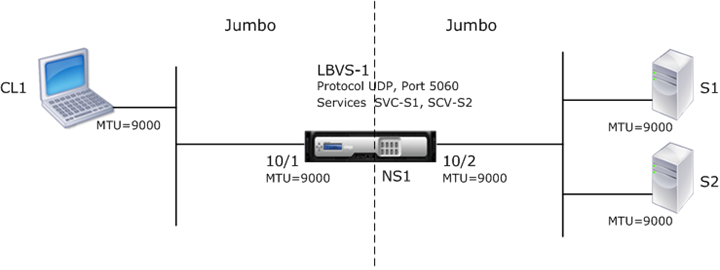
Consider an example of a jumbo to jumbo setup in which SIP load balancing virtual server LBVS-1, configured on Citrix ADC appliance NS1, is used to load balance SIP traffic across servers S1 and S2. The connection between client CL1 and NS1, and the connection between NS1 and the servers support jumbo frames.
Interface 10/1 of NS1 receives or sends traffic from or to client CL1. Interface 10/2 of NS1 receives or sends traffic from or to server S1 or S2. Interfaces 10/1 and 10/2 of NS1 are part of VLAN 10 and VLAN 20, respectively.
For supporting jumbo frames, the MTU is set to 9216, on NS1, for interfaces 10/1, 10/2, and VLANs VLAN 10, VLAN 20.
All other network devices, including CL1, S1, S2, in this setup example are also configured for supporting jumbo frames.
The following table lists the settings used in the example.
| Entity | Name | Details |
|---|---|---|
| IP address of client CL1 | - | 192.0.2.10 |
| IP address of servers | S1 | 198.51.100.19 |
| S2 | ||
| SNIP address on NS1 | 198.51.100.18 | |
| MTU specified for interfaces and VLANs on NS1 | 10/1 | 9000 |
| 10/2 | ||
| VLAN 10 | ||
| VLAN 20 | ||
| Services on NS1 representing servers | SVC-S1 | IP address: 198.51.100.19, Protocol: SIP, Port: 5060 |
| SVC-S2 | ||
| Load balancing virtual server on VLAN 10 | LBVS-1 | IP address: 203.0.113.15, Protocol: SIP, Port: 5060, Bound services: SVC-S1, SVC-S2 |
Following is the traffic flow of CL1’s request to NS1:
- CL1 creates a 20000-byte SIP request to send to LBVS-1 of NS1.
-
CL1 sends the request data in IP fragments to LBVS-1. The size of each IP fragment is either equal to or less than the MTU (9000) set on the interface from which CL1 sends these fragments to NS1.
- Size of the first IP fragment = [IP header + UDP header + SIP data segment] = [20 + 8 + 8972] = 9000
- Size of the second IP fragment = [IP header + SIP data segment] = [20 + 8980] = 9000
- Size of the last IP fragment=[IP header + SIP data segment] = [20 + 2048] = 2068
- NS1 receives the request IP fragments at interface 10/1. NS1 accepts these fragments, because the size of each of these fragments is equal to or less than the MTU (9000) of interface 10/1.
- NS1 reassembles these IP fragments to form the 20000-byte SIP request. NS1 processes this request.
- LBVS-1’s load balancing algorithm selects server S1.
-
NS1 sends the request data in IP fragments to S1. The size of each IP fragment is either equal or less than the MTU (9000) of the interface 10/2, from which NS1 sends these fragments to S1. The IP packets are sourced with a SNIP address of NS1.
- Size of the first IP fragment = [IP header + UDP header + SIP data segment] = [20 + 8 + 8972] = 9000
- Size of the second IP fragment = [IP header + SIP data segment] = [20 + 8980] = 9000
- Size of the last IP fragment=[IP header + SIP data segment] = [20 + 2048] = 2068
Following is the traffic flow of S1’s response to CL1 in this example:
- Server S1 creates a 30000-byte SIP response to send to the SNIP address of NS1.
-
S1 sends the response data in IP fragments to the SNIP address of NS1. The size of each IP fragment is either equal to or less than the MTU (9000) set on the interface from which S1 sends these fragments to NS1.
- Size of the first IP fragment = [IP header + UDP header + SIP data segment] = [20 + 8 + 8972] = 9000
- Size of the second and third IP fragment = [IP header + SIP data segment] = [20 + 8980] = 9000
- Size of the last IP fragment=[IP header + SIP data segment] = [20 + 3068] = 3088
- NS1 receives the response IP fragments at interface 10/2. NS1 accepts these fragments, because the size of each fragment is equal to or less than the MTU (9000) of interface 10/2.
- NS1 reassembles these IP fragments to form the 30000-byte SIP response. NS1 processes this response.
-
NS1 sends the response data in IP fragments to CL1. The size of each IP fragment is either equal or less than the MTU (9000) of the interface 10/1, from which NS1 sends these fragments to CL1. The IP fragments are sourced with LBVS-1’s IP address.
- Size of the first IP fragment = [IP header + UDP header + SIP data segment] = [20 + 8 + 8972] = 9000
- Size of the second and third IP fragment = [IP header + SIP data segment] = [20 + 8980] = 9000
- Size of the last IP fragment=[IP header + SIP data segment] = [20 + 3068] = 3088
Configuration Tasks
The following table list the tasks, Citrix ADC commands, and examples for creating the required configuration on the Citrix ADC appliance.
| Task | Citrix ADC Command Syntax | Example |
|---|---|---|
| Set the MTU of the desired interfaces for supporting jumbo frames | set interface |
set int 10/1 -mtu 9000 set int 10/2 -mtu 9000 |
| Create VLANs and set the MTU of the desired VLANs for supporting jumbo frames | add vlan |
add vlan 10 -mtu 9000 add vlan 20 -mtu 9000 |
| Bind interfaces to VLANs | bind vlan |
bind vlan 10 -ifnum 10/1 bind vlan 20 -ifnum 10/2 |
| Add a SNIP address | add ns ip |
add ns ip 198.51.100.18 255.255.255.0 -type SNIP |
| Create services representing SIP servers | add service |
add service SVC-S1 198.51.100.19 SIP_UDP 5060 add service SVC-S2 198.51.100.20 SIP_UDP 5060 |
| Create SIP load balancing virtual servers and bind the services to it | add lb vserver |
add lb vserver LBVS-1 SIP_UDP 203.0.113.15 5060 bind lb vserver LBVS-1 SVC-S1 bind lb vserver LBVS-1 SVC-S2 |
| Save the configuration | save ns config, show ns config |