-
Getting Started with Citrix ADC
-
Deploy a Citrix ADC VPX instance
-
Install a Citrix ADC VPX instance on Microsoft Hyper-V servers
-
Install a Citrix ADC VPX instance on Linux-KVM platform
-
Prerequisites for Installing Citrix ADC VPX Virtual Appliances on Linux-KVM Platform
-
Provisioning the Citrix ADC Virtual Appliance by using OpenStack
-
Provisioning the Citrix ADC Virtual Appliance by using the Virtual Machine Manager
-
Configuring Citrix ADC Virtual Appliances to Use SR-IOV Network Interface
-
Configuring Citrix ADC Virtual Appliances to use PCI Passthrough Network Interface
-
Provisioning the Citrix ADC Virtual Appliance by using the virsh Program
-
Provisioning the Citrix ADC Virtual Appliance with SR-IOV, on OpenStack
-
Configuring a Citrix ADC VPX Instance on KVM to Use OVS DPDK-Based Host Interfaces
-
-
Deploy a Citrix ADC VPX instance on Microsoft Azure
-
Network architecture for Citrix ADC VPX instances on Microsoft Azure
-
Configure multiple IP addresses for a Citrix ADC VPX standalone instance
-
Configure a high-availability setup with multiple IP addresses and NICs
-
Configure a high-availability setup with multiple IP addresses and NICs by using PowerShell commands
-
Configure HA-INC nodes by using the Citrix high availability template with Azure ILB
-
Configure address pools (IIP) for a Citrix Gateway appliance
-
-
Upgrade and downgrade a Citrix ADC appliance
-
Solutions for Telecom Service Providers
-
Load Balance Control-Plane Traffic that is based on Diameter, SIP, and SMPP Protocols
-
Provide Subscriber Load Distribution Using GSLB Across Core-Networks of a Telecom Service Provider
-
Authentication, authorization, and auditing application traffic
-
Configuring authentication, authorization, and auditing policies
-
Configuring Authentication, authorization, and auditing with commonly used protocols
-
Use an on-premises Citrix Gateway as the identity provider for Citrix Cloud
-
Troubleshoot authentication issues in Citrix ADC and Citrix Gateway with aaad.debug module
-
-
-
-
-
-
Persistence and persistent connections
-
Advanced load balancing settings
-
Gradually stepping up the load on a new service with virtual server–level slow start
-
Protect applications on protected servers against traffic surges
-
Retrieve location details from user IP address using geolocation database
-
Use source IP address of the client when connecting to the server
-
Use client source IP address for backend communication in a v4-v6 load balancing configuration
-
Set a limit on number of requests per connection to the server
-
Configure automatic state transition based on percentage health of bound services
-
-
Use case 2: Configure rule based persistence based on a name-value pair in a TCP byte stream
-
Use case 3: Configure load balancing in direct server return mode
-
Use case 6: Configure load balancing in DSR mode for IPv6 networks by using the TOS field
-
Use case 7: Configure load balancing in DSR mode by using IP Over IP
-
Use case 10: Load balancing of intrusion detection system servers
-
Use case 11: Isolating network traffic using listen policies
-
Use case 14: ShareFile wizard for load balancing Citrix ShareFile
-
-
-
-
-
Authentication and authorization
-
-
Configuring a CloudBridge Connector Tunnel between two Datacenters
-
Configuring CloudBridge Connector between Datacenter and AWS Cloud
-
Configuring a CloudBridge Connector Tunnel Between a Datacenter and Azure Cloud
-
Configuring CloudBridge Connector Tunnel between Datacenter and SoftLayer Enterprise Cloud
-
Configuring a CloudBridge Connector Tunnel Between a Citrix ADC Appliance and Cisco IOS Device
-
CloudBridge Connector Tunnel Diagnostics and Troubleshooting
-
-
Synchronizing Configuration Files in a High Availability Setup
-
Restricting High-Availability Synchronization Traffic to a VLAN
-
Understanding the High Availability Health Check Computation
-
Managing High Availability Heartbeat Messages on a Citrix ADC Appliance
-
Remove and Replace a Citrix ADC in a High Availability Setup
This content has been machine translated dynamically.
Dieser Inhalt ist eine maschinelle Übersetzung, die dynamisch erstellt wurde. (Haftungsausschluss)
Cet article a été traduit automatiquement de manière dynamique. (Clause de non responsabilité)
Este artículo lo ha traducido una máquina de forma dinámica. (Aviso legal)
此内容已动态机器翻译。 放弃
このコンテンツは動的に機械翻訳されています。免責事項
This content has been machine translated dynamically.
This article has been machine translated.
Dieser Artikel wurde maschinell übersetzt. (Haftungsausschluss)
Ce article a été traduit automatiquement. (Clause de non responsabilité)
Este artículo ha sido traducido automáticamente. (Aviso legal)
この記事は機械翻訳されています.免責事項
이 기사는 기계 번역되었습니다.
Este artigo foi traduzido automaticamente.
这篇文章已经过机器翻译.放弃
Translation failed!
Use Case 2 – Non-Jumbo to Jumbo Setup
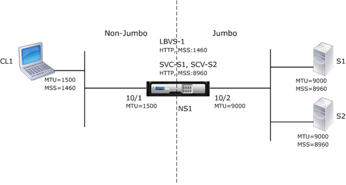
Consider an example of a regular to jumbo setup in which load balancing virtual server LBVS-1, configured on a Citrix ADC appliance NS1, is used to load balance traffic across servers S1 and S2. The connection between client CL1 and NS1 supports regular frames, and the connection between NS1 and the servers supports jumbo frames.
Interface 10/1 of NS1 receives or sends traffic from or to client CL1. Interface 10/2 of NS1 receives or sends traffic from or to server S1 or S2.
Interfaces 10/1 and 10/2 of NS1 are part of VLAN 10 and VLAN 20, respectively. For supporting only regular frames between CL1 and NS1, the MTU is set to the default value of 1500 for both interface 10/1 and VLAN 10
For supporting jumbo frames between NS1 and the servers, the MTU is set to 9000 for interface 10/2 and VLAN 20. Servers and all other network devices between NS1 and the servers are also configured for supporting jumbo frames.
Since HTTP traffic is based on TCP, MSSs are set accordingly at each end point for supporting jumbo frames.
- For supporting jumbo frames for the connection between a SNIP address of NS1 and S1 or S2, the MSS on NS1 is set accordingly in a custom TCP profile, which is bound to the services (SVC-S1 and SVC-S1 ) representing S1 and S2 on NS1.
- For supporting only regular frames for the connection between CL1 and virtual server LBVS-1 of NS1, default TCP profile nstcp_default_profile is used that is by default bound to LBVS-1 and has the MSS set to the default value of 1460.
The following table lists the settings used in this example.
Entity | Name | Details |
---|---|---|
IP address of client CL1 | 192.0.2.10 | |
IP address of servers | S1 | 198.51.100.19 |
S2 | 198.51.100.20 | |
SNIP address on NS1 | 198.51.100.18 | |
MTU specified for interfaces and VLANs on NS1 | 10/1 | 1500 |
10/2 | 9000 | |
VLAN 10 | 1500 | |
VLAN 20 | 9000 | |
Default TCP profile | nstcp_default_profile | MSS:1460 |
Custom TCP profile | NS1-SERVERS-JUMBO | MSS: 8960 |
Services on NS1 representing servers | SVC-S1 | IP address: 198.51.100.19, Protocol: HTTP, Port: 80, TCP profile: NS1-SERVERS-JUMBO (MSS: 8960) |
SVC-S2 | IP address: 198.51.100.20, Protocol: HTTP, Port: 80, TCP profile: NS1-SERVERS-JUMBO (MSS: 8960) | |
Load balancing virtual server on VLAN 10 | LBVS-1 | IP address = 203.0.113.15, Protocol: HTTP, Port:80, Bound services: SVC-S1, SVC-S2, TCP Profile: nstcp_default_profile (MSS:1460) |
Following is the traffic flow of CL1’s request to S1 in this example:
-
Client CL1 creates a 200-byte HTTP request to send to virtual server LBVS-1 of NS1.
-
CL1 opens a connection to LBVS-1 of NS1. CL1 and NS1 exchange their respective TCP MSS values while establishing the connection.
-
Because NS1’s MSS is larger than the HTTP request, CL1 sends the request data in a single IP packet to NS1.
Size of the request packet = [IP Header + TCP Header + TCP Request] = [20 + 20 + 200] = 240
-
NS1 receives the request packet at interface 10/1 and then processes the HTTP request data in the packet.
-
LBVS-1’s load balancing algorithm selects server S1, and NS1 opens a connection between one of its SNIP addresses and S1. NS1 and CL1 exchange their respective TCP MSS values while establishing the connection.
-
Because S1’s MSS is larger than the HTTP request, NS1 sends the request data in a single IP packet to S1.
Size of the request packet = [IP Header + TCP Header + [TCP Request] = [20 + 20 + 200] = 240
Following is the traffic flow of S1’s response to CL1 in this example:
- Server S1 creates an 18000-byte HTTP response to send to the SNIP address of NS1.
-
S1 segments the response data into multiples of NS1’s MSS and sends these segments in IP packets to NS1. These IP packets are sourced from S1’s IP address and destined to the SNIP address of NS1.
- Size of the first two packet = [IP Header + TCP Header + (TCP segment=NS1’s MSS size)] = [20 + 20 + 8960] = 9000
- Size of the last packet = [IP Header + TCP Header + (remaining TCP segment)] = [20 + 20 + 2080] = 2120
- NS1 receives the response packets at interface 10/2.
- From these IP packets, NS1 assembles all the TCP segments to form the HTTP response data of 18000 bytes. NS1 processes this response.
-
NS1 segments the response data into multiples of CL1’s MSS and sends these segments in IP packets, from interface 10/1, to CL1. These IP packets are sourced from LBVS-1’s IP address and destined to CL1’s IP address.
- Size of all packets except the last one = [IP Header + TCP Header + (TCP payload=CL1’s MSS size)] = [20 + 20 + 1460] = 1500
- Size of the last packet = [IP Header + TCP Header + (remaining TCP segment)] = [20 + 20 + 480] = 520
Configuration Tasks
The following table list the tasks, Citrix ADC commands, and examples for creating the required configuration on the Citrix ADC appliance.
Tasks | CLI Syntax | Examples |
---|---|---|
Set the MTU of the desired interfaces for supporting jumbo frames | set interface <id> -mtu <positive_integer>, show interface <id> | set int 10/1 -mtu 1500 set int 10/2 -mtu 9000 |
Create VLANs and set the MTU of the desired VLANs for supporting jumbo frames | add vlan <id> -mtu <positive_integer>, show vlan <id> | add vlan 10 -mtu 1500 add vlan 20 -mtu 9000 |
Bind interfaces to VLANs | bind vlan <id> -ifnum <interface_name>, show vlan <id> | bind vlan 10 -ifnum 10/1 bind vlan 20 -ifnum 10/2 |
Add a SNIP address | add ns ip <IPAddress> <netmask> -type SNIP, show ns ip | add ns ip 198.51.100.18 255.255.255.0 -type SNIP |
Create services representing HTTP servers | add service <serviceName> <ip> HTTP <port>, show service <name> | add service SVC-S1 198.51.100.19 http 80, add service SVC-S2 198.51.100.20 http 80 |
Create HTTP load balancing virtual servers and bind the services to it | add lb vserver <name> HTTP <ip> <port>, bind lb vserver <vserverName> <serviceName>, show lb vserver <name> | add lb vserver LBVS-1 http 203.0.113.15 80, bind lb vserver LBVS-1 SVC-S1, bind lb vserver LBVS-1 SVC-S2 |
Create a custom TCP profile and set its MSS for supporting jumbo frames | add tcpProfile <name> -mss <positive_integer>, show tcpProfile <name> | add tcpprofile NS1-SERVERS-JUMBO -mss 8960 |
Bind the custom TCP profile to the desired services | set service <Name> -tcpProfileName <string>, show service <name> | set service SVC-S1 -tcpProfileName NS1-SERVERS-JUMBO, set service SVC-S2 -tcpProfileName NS1-SERVERS-JUMBO |
Save the configuration | save ns config, show ns config |
Share
Share
In this article
This Preview product documentation is Citrix Confidential.
You agree to hold this documentation confidential pursuant to the terms of your Citrix Beta/Tech Preview Agreement.
The development, release and timing of any features or functionality described in the Preview documentation remains at our sole discretion and are subject to change without notice or consultation.
The documentation is for informational purposes only and is not a commitment, promise or legal obligation to deliver any material, code or functionality and should not be relied upon in making Citrix product purchase decisions.
If you do not agree, select Do Not Agree to exit.