Use Case 3 – Coexistence of Jumbo and Non-Jumbo flows on the Same Set of Interfaces
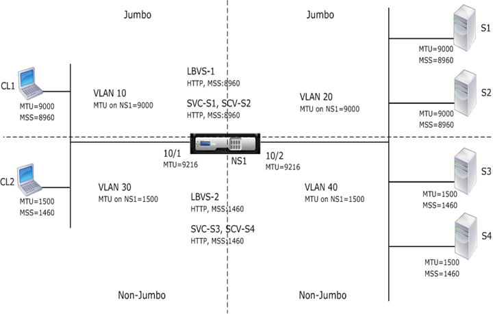
Consider an example in which load balancing virtual servers LBVS-1 and LBVS-2 are configured on Citrix ADC appliance NS1. LBVS-1 is used to load balance HTTP traffic across servers S1 and S2, and LBVS-2 is used to load balance traffic across servers S3 and S4.
CL1 is on VLAN 10, S1 and S2 are on VLAN20, CL2 is on VLAN 30, and S3 and S4 are on VLAN 40. VLAN 10 and VLAN 20 support jumbo frames, and VLAN 30 and VLAN 40 support only regular frames.
In other words, the connection between CL1 and NS1, and the connection between NS1 and server S1 or S2 support jumbo frames. The connection between CL2 and NS1, and the connection between NS1 and server S3 or S4 support only regular frames.
Interface 10/1 of NS1 receives or sends traffic from or to clients. Interface 10/2 of NS1 receives or sends traffic from or to the servers.
Interface 10/1 is bound to both VLAN 10 and VLAN 30 as a tagged interface, and interface 10/2 is bound to both VLAN 20 and VLAN 40 as a tagged interface.
For supporting jumbo frames, the MTU is set to 9216 for interfaces 10/1 and 10/2.
On NS1, the MTU is set to 9000 for VLAN 10 and VLAN 20 for supporting jumbo frames, and the MTU is set to the default value of 1500 for VLAN 30 and VLAN 40 for supporting only regular frames.
The effective MTU on a Citrix ADC interface for VLAN tagged packets is of the MTU of the interface or the MTU of the VLAN, whichever is lower. For example:
- The MTU of interface 10/1 is 9216. The MTU of VLAN 10 is 9000. On interface 10/1, the MTU of VLAN 10 tagged packets is 9000.
- The MTU of interface 10/2 is 9216. The MTU of VLAN 20 is 9000. On interface 10/2, the MTU of VLAN 20 tagged packets is 9000.
- The MTU of interface 10/1 is 9216. The MTU of VLAN 30 is 1500. On interface 10/1, the MTU of VLAN 30 tagged packets is 1500.
- The MTU of interface 10/2 is 9216. The MTU of VLAN 40 is 1500. On interface 10/2, the MTU of VLAN 40 tagged packets is 9000.
CL1, S1, S2, and all network devices between CL1 and S1 or S2 are configured for jumbo frames.
Since HTTP traffic is based on TCP, MSSs are set accordingly at each end point for supporting jumbo frames.
- For the connection between CL1 and virtual server LBVS-1 of NS1, the MSS on NS1 is set in a TCP profile, which is then bound to LBVS-1.
- For the connection between a SNIP address of NS1 and S1, the MSS on NS1 is set in a TCP profile, which is then bound to the service (SVC-S1) representing S1 on NS1.
The following table lists the settings used in this example: Jumbo frames use case 3 example settings.
Following is the traffic flow of CL1’s request to S1:
- Client CL1 creates a 20000-byte HTTP request to send to virtual server LBVS-1 of NS1.
- CL1 opens a connection to LBVS-1 of NS1. CL1 and NS1 exchange their TCP MSS values while establishing the connection.
- Because NS1’s MSS value is smaller than the HTTP request, CL1 segments the request data into multiples of NS1’s MSS and sends these segments in IP packets tagged as VLAN 10 to NS1.
- Size of the first two packets = [IP Header + TCP Header + (TCP segment=NS1 MSS)] = [20 + 20 + 8960] = 9000
- Size of the last packet = [IP Header + TCP Header + (remaining TCP segment)] = [20 + 20 + 2080] = 2120
- NS1 receives these packets at interface 10/1. NS1 accepts these packets because the size of these packets is equal to or less than the effective MTU (9000) of interface 10/1 for VLAN 10 tagged packets.
- From the IP packets, NS1 assembles all the TCP segments to form the 20000-byte HTTP request. NS1 processes this request.
- LBVS-1’s load balancing algorithm selects server S1, and NS1 opens a connection between one of its SNIP addresses and S1. NS1 and CL1 exchange their respective TCP MSS values while establishing the connection.
- NS1 segments the request data into multiples of S1’s MSS and sends these segments in IP packets tagged as VLAN 20 to S1.
- Size of the first two packets = [IP Header + TCP Header + (TCP payload=S1 MSS)] = [20 + 20 + 8960] = 9000
- Size of the last packet = [IP Header + TCP Header + (remaining TCP segment)] = [20 + 20 + 2080] = 2120
Following is the traffic flow of S1’s response to CL1:
- Server S1 creates a 30000-byte HTTP response to send to the SNIP address of NS1.
- S1 segments the response data into multiples of NS1’s MSS and sends these segments in IP packets tagged as VLAN 20 to NS1. These IP packets are sourced from S1’s IP address and destined to the SNIP address of NS1.
- Size of first three packet = [IP Header + TCP Header + (TCP segment=NS1’s MSS size)] = [20 + 20 + 8960] = 9000
- Size of the last packet = [IP Header + TCP Header + (remaining TCP segment)] = [20 + 20 + 3120] = 3160
- NS1 receives the response packets at interface 10/2. NS1 accepts these packets, because their size is equal to or less than the effective MTU value (9000) of interface 10/2 for VLAN 20 tagged packets.
- From these IP packets, NS1 assembles all the TCP segments to form the 30000-byte HTTP response. NS1 processes this response.
- NS1 segments the response data into multiples of CL1’s MSS and sends these segments in IP packets tagged as VLAN 10, from interface 10/1, to CL1. These IP packets are sourced from LBVS’s IP address and destined to CL1’s IP address.
- Size of first three packet = [IP Header + TCP Header + [(TCP payload=CL1’s MSS size)] = [20 + 20 + 8960] = 9000
- Size of the last packet = [IP Header + TCP Header + (remaining TCP segment)] = [20 + 20 + 3120] = 3160
Configuration Tasks
Following table lists tasks, commands, and examples for creating the required configuration on the Citrix ADC appliance: Jumbo frames use case 3 configuration tasks.