Configuring Subnet IP Addresses (SNIPs)
A subnet IP address (SNIP) is a Citrix ADC owned IP address that is used by the Citrix ADC to communicate with the servers.
The Citrix ADC uses the subnet IP address as a source IP address to proxy client connections to servers. It also uses the subnet IP address when generating its own packets, such as packets related to dynamic routing protocols, or to send monitor probes to check the health of the servers. Depending on your network topology, you might have to configure one or more SNIPs for different scenarios.
To configure a SNIP address on a Citrix ADC, you add the SNIP address and then enable global Use Subnet IP (USNIP) mode. As an alternative to creating SNIPs one at a time, you can specify a consecutive range of SNIPs.
To configure a SNIP address by using the CLI:
At the command prompt, type:
- add ns ip <IPAddress> <netmask> -type SNIP
- show ns ip <IPAddress>
Example:
> add ns ip 10.102.29.203 255.255.255.0 -type SNIP
 Done
<!--NeedCopy-->
To create a range of SNIP addresses by using the CLI:
At the command prompt, type:
- add ns ip <IPAddress> <netmask> -type SNIP
- show ns ip <IPAddress>
Example:
> add ns ip 10.102.29.[205-209] 255.255.255.0 -type SNIP
ip "10.102.29.205" added
ip "10.102.29.206" added
ip "10.102.29.207" added
ip "10.102.29.208" added
ip "10.102.29.209" added
 Done
<!--NeedCopy-->
To enable or disable USNIP mode by using the CLI:
At the command prompt, type one of the following commands:
- enable ns modeUSNIP
- disable ns modeUSNIP
To configure a SNIP address by using the GUI:
Navigate to System > Network > IPs > IPV4s, and add a new SNIP address or edit an existing address.
To create a range of SNIP addresses by using the GUI:
- Navigate to System > Network > IPs > IPV4s.
- In the Action list, select Add Range.
To enable or disable USNIP mode by using the CLI:
At the command prompt, type one of the following commands:
-
enable ns mode USNIP
-
disable ns mode USNIP
To enable or disable USNIP mode by using the GUI:
- Navigate to System > Settings, in Modes and Features group, click Change modes.
- Select or clear the Use Subnet IP option.
Using SNIPs for a Directly Connected Server Subnet
To enable communication between the Citrix ADC and a server that is either connected directly to the Citrix ADC or connected through only an L2 switch, you must configure a subnet IP address that belongs to the subnet of the server. You must configure at least one subnet IP address for each directly connected subnet, except for the directly connected management subnet that is connected through NSIP.
Consider an example of a load balancing setup in which load balancing virtual server LBVS1 on Citrix ADC NS1 is used to load balance servers S1 and S2, which are connected to NS1 through L2 switch SW1. S1 and S2 belong to the same subnet.
SNIP address SNIP1, which belongs to the same subnet as S1 and S2, is configured on NS1. As soon as SNIP1 is configured, NS1 broadcasts ARP packets for SNIP1.
Services SVC-S1 and SVC-S2 on NS1 represent S1 and S2. As soon as these services are configured, NS1 broadcasts ARP requests for S1 and S2 to resolve IP-to-MAC mapping. After S1 and S2 respond, NS1 sends them monitoring probes at regular intervals, from address SNIP1, to check their health.
For more information about configuring load balancing on a Citrix ADC, see Load Balancing.
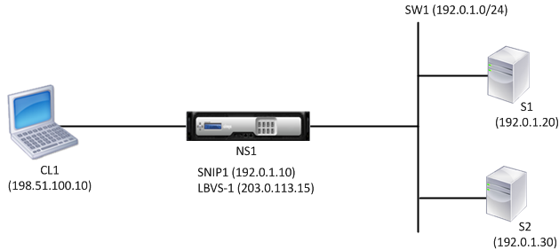
Following is the traffic flow in this example:
- Client C1 sends a request packet to LBVS-1. The request packet has:
- Source IP = IP address of the client (198.51.100.10)
- Destination IP = IP address of LBVS-1 (203.0.113.15)
- LBVS1 of NS1 receives the request packet.
- LBVS1’s load balancing algorithm selects server S2.
- Because S2 is directly connected to NS1, and SNIP1 (192.0.1.10) is the only IP address on NS1 that belongs to the same subnet as S2, NS1 opens a connection between SNIP1 and S2.
- NS1 sends the request packet to S2 from SNIP1. The request packet has:
- Source IP = SNIP1 (192.0.1.10)
- Destination IP = IP address of S2 (192.0.1.30)
- S2’s response returns by the same path.
Using SNIPs for Server Subnets Connected through a Router
To enable communication between the Citrix ADC and servers in subnets connected through a router, you must configure at least one subnet IP address that belongs to the subnet of the directly connected interface to the router. The ADC uses this subnet IP address to communicate with servers in subnets that can be reached through the router.
Consider an example of a load balancing setup in which load balancing virtual server LBVS1 on Citrix ADC NS1 is used to load balance servers S1, S2, S3, and S4, which are connected to NS1 through router R1.
S1 and S2 belong to same subnet, 192.0.2.0/24, and are connected to R1 through L2 switch SW1. S3 and S4 belong to a different subnet, 192.0.3.0/24, and are connected to R1 through L2 switch SW2.
Citrix ADC NS1 is connected to router R1 through subnet 192.0.1.0/24. SNIP address SNIP1, which belongs to the same subnet as the directly connected interface to the router (192.0.1.0/24), is configured on NS1. NS1 uses this address to communicate with servers S1 and S2, and with servers S3 and S4.
For more information about configuring load balancing on a Citrix ADC, see Load Balancing.
As soon as address SNIP1 is configured, NS1 broadcasts ARP announcement packets for SNIP1.
NS1’s routing table consists of route entries for S1, S2, S3, and S4 through R1. These route entries are either static route entries or advertised by R1 to NS1, using dynamic routing protocols.
Services SVC-S1, SVC-S2, SVC-S3, and SVC-S4 on NS1 represent servers S1, S2, S3, and S4. NS1 finds, in its routing tables, that these servers are reachable through R1. NS1 sends them monitoring probes at regular intervals, from address SNIP1, to check their health.
For more information about IP routing on a Citrix ADC, see IP Routing.
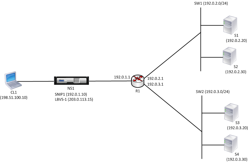
Following is the traffic flow in this example:
- Client C1 sends a request packet to LBVS-1. The request packet has:
- Source IP = IP address of the client (198.51.100.10)
- Destination IP = IP address of LBVS-1 (203.0.113.15)
- LBVS1 of NS1 receives the request packet.
- LBVS1’s load balancing algorithm selects server S3.
- NS1 checks its routing table and finds that S3 is reachable through R1. SNIP1 (192.0.1.10) is the only IP address on NS1 that belongs to the same subnet as router R1, NS1 opens a connection between SNIP1 and S3 through R1.
- NS1 sends the request packet to R1 from SNIP1. The request packet has:
- Source IP address = SNIP1 (192.0.1.10)
- Destination IP address = IP address of S3 (192.0.3.20)
- The request reaches R1, which checks its routing table and forwards the request packet to S3.
- S3’s response returns by the same path.
Using SNIPs for Multiple Server Subnets (VLANs) on an L2 Switch
When you have multiple server subnets (VLANs) on an L2 switch that is connected to a Citrix ADC, you must configure at least one SNIP address for each of the server subnets, so that the Citrix ADC can communicate with these server subnets.
Consider an example of a load balancing setup in which load balancing virtual server LBVS1 on Citrix ADC NS1 is used to load balance servers S1 and S2, which are connected to NS1 through L2 switch SW1. S1 and S2 belong to different subnets and are part of VLAN 10 and VLAN20, respectively. The link between NS1 and SW1 is a trunk link and is shared by VLAN10 and VLAN20.
For more information about configuring load balancing on a Citrix ADC, see Load Balancing.
Subnet IP addresses SNIP1 (for reference purposes only) and SNIP2 (for reference purposes only) are configured on NS1. NS1 uses SNIP1 (on VLAN 10) to communicate with server S1, and SNIP2 (on VLAN 20) to communicate with S2. As soon as SNIP1 and SNIP2 are configured, NS1 broadcasts ARP announcement packets for SNIP1 and SNIP2.
For more information about configuring VLANs on a Citrix ADC, see Configuring a VLAN.
Services SVC-S1 and SVC-S2 on NS1 represent servers S1 and S2. As soon as these services are configured, NS1 broadcasts ARP requests for them. After S1 and S2 respond, NS1 sends them monitoring probes at regular intervals to check their health. NS1 sends monitoring probes to S1 from address SNIP1, and to S2 from address SNIP2.
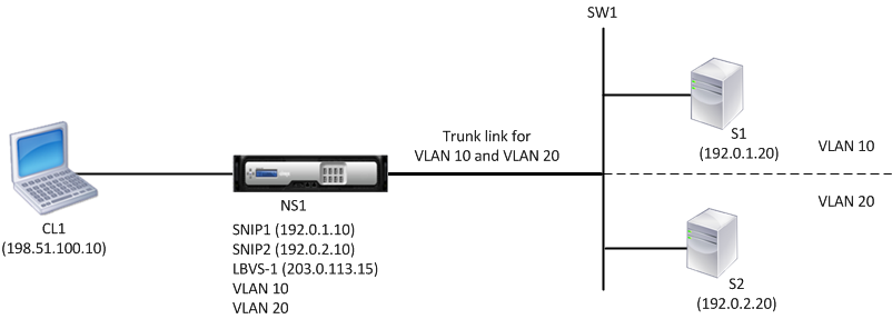
Following is the traffic flow in this example:
- Client C1 sends a request packet to LBVS-1. The request packet has:
- Source IP = IP address of the client (198.51.100.10)
- Destination IP = IP address of LBVS-1 (203.0.113.15)
- LBVS1 of NS1 receives the request packet.
- LBVS1’s load balancing algorithm selects server S2.
- Because S2 is directly connected to NS1, and SNIP2 (192.0.2.10) is the only IP address on NS1 that belongs to the same subnet as S2, NS1 opens a connection between SNIP2 and S2. Note: If S1 is selected, NS1 opens a connection between SNIP1 and S1.
- NS1 sends the request packet to S2 from SNIP2. The request packet has:
- Source IP = SNIP1 (192.0.2.10)
- Destination IP = IP address of S2 (192.0.2.20)
- S2’s response returns by the same path.