Traffic Domains
Warning
Citrix recommends you to use Admin Partitions instead of using Traffic Domains. For more information, see Admin Partitioning page.
Traffic domains are a way to segment network traffic for different applications. You can use traffic domains to create multiple isolated environments within a Citrix ADC appliance. An application belonging to a specific traffic domain communicates with entities and processes traffic within that domain. The traffic belonging to one traffic domain cannot cross the boundary of another traffic domain.
Benefits of using Traffic Domains
The main benefits of using traffic domains on a Citrix ADC appliance are the following:
- Use of duplicate IP addresses in a Network. Traffic domains allow you to use duplicate IP address on the network. You can assign the same IP address or network address to multiple devices on a network, or multiple entities on a Citrix ADC appliance, as long as each of the duplicate address belongs to a different traffic domain.
- Use of Duplicate entities on the Citrix ADC appliance. Traffic domains also allow you to use duplicate Citrix ADC feature entities on the appliance. You can create entities with the same settings as long as each entity is assigned to a separate traffic domain. Note: Duplicate entities with same name are not supported.
- Multitenancy. Using traffic domains, you can provide hosting services for multiple customers by isolating each customer’s type of application traffic within a defined address space on the network.
A traffic domain is uniquely identified by an identifier, which is an integer value. Each traffic domain needs a VLAN or a set of VLANs. The isolation functionality of the traffic domain depends on the VLANs bound to the traffic domain. More than one VLAN can be bound to a traffic domain, but the same VLAN cannot be a part of multiple traffic domains. Therefore, the maximum number of traffic domains that can be created depends on the number of VLANS configured on the appliance.
Default Traffic Domain
A Citrix ADC appliance has a preconfigured traffic domain, called the default traffic domain, which has an ID of 0. All factory settings and configurations are part of the default traffic domain. You can create other traffic domains and then segment traffic between the default traffic domain and each of the other traffic domains. You cannot remove the default traffic domain from the Citrix ADC appliance. Any feature entity that you create without setting the traffic domain ID is automatically associated with the default traffic domain.
Note: Some features and configurations are supported only in the default traffic domain. They do not work in nondefault traffic domains. For a list of the features supported in all traffic domains, see Supported Citrix ADC Features in Traffic Domains.
How Traffic Domains Work
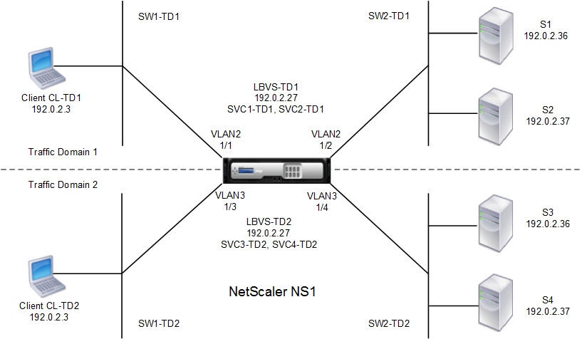
As an illustration of traffic domains, consider an example in which two traffic domains, with IDs 1 and 2, are configured on Citrix ADC appliance NS1.
In traffic domain 1, load balancing virtual server LBVS-TD1 is configured to load balance traffic across servers S1 and S2. On the Citrix ADC appliance, servers S1 and S2 are represented by services SVC1-TD1 and SVC2-TD1, respectively. Servers S1 and S2 are connected to NS1 through L2 switch SW2-TD1. Client CL-TD1 is on a private network connected to NS1 through L2 switch SW1-TD1. SW1-TD1 and SW2-TD1 are connected to VLAN 2 of NS1. VLAN 2 is bound to traffic domain 1, which means that client CL-TD1 and servers S1 and S2 are part of traffic domain 1.
Similarly in traffic domain 2, load balancing virtual server LBVS-TD2 is configured to load balance traffic across S3 and S4. On the Citrix ADC appliance, servers S3 and S4 are represented by services SVC3-TD2 and SVC4-TD2, respectively. Servers S3 and S4 are connected to NS1 through L2 switch SW2-TD2. Client CL-TD2 is on a private network connected to NS1 through L2 switch SW1-TD2. SW1-TD2 and SW2-TD2 are connected to VLAN 3 of NS1. VLAN 3 is bound to traffic domain 2, which means that client CL-TD2 and servers S3 and S4 are part of traffic domain 2.
On the Citrix ADC appliance, entities LBVS-TD1 and LBVS-TD2 share the same settings, including the IP address. The same is true for SVC1-TD1 and SVC3-TD2, and for SVC2-TD1 and SVC4-TD2. This is possible because these entities are in different traffic domains.
Similarly, servers S1 and S3, S2 and S4 share the same IP address, and clients CL-TD1 and CL-TD2 each have the same IP address.
Figure 1. How traffic domains work
The following table lists the settings used in the example.
| Entity | Name | Details |
|---|---|---|
| Settings in traffic domain 1 | ||
| VLANs bound to traffic domain 1 | VLAN 2 | VLAN Id: 2 Interfaces bound: 1/1, 1/2 |
| Client connected to TD1 | CL-TD1 (for reference purposes only) | IP address: 192.0.2.3 |
| Load balancing virtual server in TD1 | LBVS-TD1 | IP address: 192.0.2.27 |
| Service bound to virtual server LBVS-TD1 | SVC1-TD1 | IP address: 192.0.2.36 |
| Service bound to virtual server LBVS-TD1 | SVC2-TD1 | IP address: 192.0.2.37 |
| SNIP | SNIP-TD1 (for reference purposes only) | IP address: 192.0.2.27 |
| Settings in traffic domain 2 | ||
| VLAN bound to traffic domain 2 | VLAN 3 | VLAN Id: 3 Interfaces bound: 1/3, 1/4 |
| Client connected to TD2 | CL-TD2 (for reference purposes only) | IP address: 192.0.2.3 |
| Load balancing virtual server in TD2 | LBVS-TD2 | IP address: 192.0.2.27 |
| Service bound to virtual server LBVS-TD2 | SVC3-TD2 | IP address: 192.0.2.36 |
| Service bound to virtual server LBVS-TD2 | SVC4-TD2 | IP address: 192.0.2.37 |
| SNIP in TD2 | SNIP-TD2 (for reference purposes only) | IP address: 192.0.2.29 |
Following is the traffic flow in traffic domain 1:
- Client CL-TD1 broadcasts an ARP request for the IP address of 192.0.2.27 through L2 switch SW1-TD1.
- The ARP request reaches NS1 on interface 1/1, which is bound to VLAN 2. Because VLAN 2 is bound to traffic domain 1, NS1 updates the ARP table of traffic domain 1 for the IP address of client CL-TD1.
- Because the ARP request is received on traffic domain 1, NS1 looks for an entity configured on traffic domain 1 that has an IP address of 192.0.2.27. NS1 finds that a load balancing virtual server LBVS-TD1 is configured on traffic domain 1 and has the IP address 192.0.2.27.
- NS1 sends an ARP response with the MAC address of interface 1/1.
- The ARP reply reaches CL-TD1. CL-TD1 updates its ARP table for the IP address of LBVS-TD1 with the MAC address of interface 1/1 of NS1.
- Client CL-TD1 sends a request to 192.0.2.27. The request is received by LBVS-TD1 on port 1/1 of NS1.
- LBVS-TD1’s load balancing algorithm selects server S2, and NS1 opens a connection between a SNIP in traffic domain 1 (192.0.2.27) and S2.
- S2 replies to SNIP 192.0.2.27 on NS1.
- NS1 sends S2’s reply to client CL-TD1.
Following is the traffic flow in traffic domain 2:
- Client CL-TD2 broadcasts an ARP request for the IP address of 192.0.2.27 through L2 switch SW1-TD2.
- The ARP request reaches NS1 on interface 1/3, which is bound to VLAN 3. Because VLAN 3 is bound to traffic domain 2, NS1 updates traffic-domain 2’s ARP-table entry for the IP address of client CL-TD2, even though an ARP entry for the same IP address (CL-TD1) is already present in the ARP table of traffic domain 1.
- Because the ARP request is received in traffic domain 2, NS1 searches traffic domain 2 for an entity that has an IP address of 192.0.2.27. NS1 finds that load balancing virtual server LBVS-TD2 is configured in traffic domain 2 and has the IP address 192.0.2.27. NS1 ignores LBVS-TD1 in traffic domain 1, even though it has the same IP address as LBVS-TD2.
- NS1 sends an ARP response with the MAC address of interface 1/3.
- The ARP reply reaches CL-TD2. CL-TD2 updates its ARP table entry for the IP address of LBVS-TD2 with the MAC address of interface 1/3 of NS1.
- Client CL-TD2 sends a request to 192.0.2.27. The request is received by LBVS-TD2 on interface 1/3 of NS1.
- LBVS-TD2’s load balancing algorithm selects server S3, and NS1 opens a connection between a SNIP in traffic domain 2 (192.0.2.29) and S3.
- S2 replies to SNIP 192.0.2.29 on NS1.
- NS1 sends S2’s reply to client CL-TD2.
Supported Citrix ADC Features in Traffic Domains
The Citrix ADC features in the following list are supported in all traffic domains.
Important
Any Citrix ADC feature not listed below is supported only in the default traffic domain.
- ARP table
- ND6 table
- Bridge table
- All types of IPv4 and IPv6 addresses
- IPv4 and IPv6 routes
- ACL and ACL6
- PBR & PBR6
- INAT
- RNAT
- RNAT6
- MSR
- MSR6
- Net profiles
- SNMP MIBs
- Fragmentation
- Monitors (Scriptable monitors are not supported)
- Content Switching
- Cache Redirection
- Persistency (Persistency groups are not supported)
- Service (Domain based services are not supported)
- Service group (Domain based service groups are not supported)
- Policies (*)
- PING
- TRACEROUTE
- PMTU
- High Availability (connection mirroring is not supported)
- Cluster (Supported on L2 clusters. Not supported on L3 clusters)
- Cookie Persistency
- MSS
- Logging (Syslog is not supported)
- Priority Queuing
- Surge Protection
- HTTP DOSP (**)
- Load balancing (The following types are not supported:)
- TFTP
- RTSP
- Diameter
- SIP
- SMPP
- NAT46
- NAT64
- DNS64
- Forwarding Session Rules
- SNMP
Note
* Policies do not have global binding points for traffic domains. However, policies can be bound to a specific load balancing virtual server of a traffic domain.
** HTTP DOSP policies do not have global binding points for traffic domains. However, HTTP DOSP policies can be bound to a specific load balancing service of a traffic domain.
Global Server Loading Balancing (GSLB) and ADNS features in Citrix ADC are not aware of Traffic Domains. If the GSLB configuration needs to be shared across all traffic domains then GSLB methods Static Proximity and Round Trip Time (RTT) do not work. As a workaround in this scenario you can use GSLB methods other than RTT and Static Proximity. For more information, see http://support.citrix.com/article/CTX202277.
Configuring Traffic Domains
Configuring a traffic domain on the Citrix ADC appliance consists of the following tasks:
- Add VLANs. Create VLANs and bind specified interfaces to them.
-
Create a traffic domain entity and bind VLANs to it. This involves the following two tasks:
- Create a traffic domain entity uniquely identified by an ID, which is an integer value.
- Bind the specified VLANs to the traffic domain entity. All the interfaces that are bound to the specified VLANs are associated with the traffic domain. More than one VLAN can be bound to a traffic domain, but a VLAN cannot be a part of multiple traffic domains.
- Create feature entities on the traffic domain. Create the required feature entities in the traffic domain. The CLI commands and configuration dialog boxes of all the supported features in a nondefault traffic domain include a parameter called a traffic domain identifier (td). When configuring a feature entity, if you want the entity to be associated with a particular traffic domain, you must specify the td. Any feature entity that you create without setting the td is automatically associated with the default traffic domain.
To give you an idea of how feature entities are associated with a traffic domain, this topic covers the procedures for configuring all the entities mentioned in the figure titled How Traffic Domains Work.
The CLI has two commands for these two tasks, but the GUI combines them in a single dialog box.
CLI procedures
To create a VLAN and bind interfaces to it by using the CLI:
At the command prompt, type:
- add vlan <id>
- bind vlan <id> -ifnum <slot/port>
- show vlan <id>
To create a traffic domain entity and bind VLANs to it by using the CLI:
At the command prompt, type:
- add ns trafficdomain <td>
- bind ns trafficdomain <td> -vlan <id>
- show ns trafficdomain <td>
To create a service by using the CLI:
At the command prompt, type:
- add service <name> <IP> <serviceType> <port> -td <id>
- show service <name>
To create a load balancing virtual server and bind services to it by using the CLI:
At the command prompt, type:
- add lb vserver <name> <serviceType> <IPAddress> <port> -td <id>
- bind lb vserver <name> <serviceName>
- show lb vserver <name>
GUI procedures
To create a VLAN by using the GUI:
Navigate to System > Network > VLANs, click Add, and set the parameters.
To create a traffic domain entity by using the GUI:
Navigate to System > Network > Traffic Domains, click Add, and in the Create Traffic Domain dialog box, set the parameters.
To create a service by using the GUI:
Navigate to Traffic Management > Load Balancing > Services, click Add, and set the parameters.
To create a load balancing virtual server by using the GUI:
Navigate to Traffic Management > Load Balancing > Virtual Servers, click Add, and set the parameters.