Subscriber aware traffic steering with TCP optimization
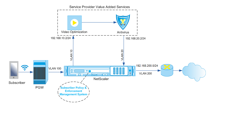
Traffic steering directs subscriber traffic from one point to another. When a subscriber connects to the network, the packet gateway associates an IP address with the subscriber and forwards the data packet to the NetScaler appliance. The appliance communicates with the PCRF server over the Gx interface to get the subscriber policy information. Depending on the policy information, the appliance performs one of the following actions:
- Forward the data packet to another set of services (as shown in the following illustration).
- Perform only TCP optimization.
The values shown in the following figure are configured in the CLI procedure that follows the figure. A content switching virtual server on the NetScaler appliance directs requests to the value added services or skips them and performs TCP optimization, depending on the defined rule, and then sends the packet out to the Internet.
Note
Support for the configuration shown below was introduced in release 11.1 build 50.10.
To configure traffic steering for the above deployment by using the CLI:
-
Add the appliance’s subnet IP (SNIP) addresses.
add ns ip 192.168.10.1 255.255.255.0 -type snip add ns ip 192.168.20.1 255.255.255.0 -type snip add ns ip 192.168.100.1 255.255.255.0 -type snip add ns ip 192.168.200.1 255.255.255.0 -type snip add ns ip 10.102.232.236 255.255.255.0 –type snip <!--NeedCopy--> -
Add the VLANs. VLANs help the appliance identify the source of the traffic. Bind the VLANs to the interfaces and subnet IP addresses.
add vlan 10 add vlan 20 add vlan 100 add vlan 200 add vlan 102 bind vlan 10 -ifnum 1/4 -tagged -IPAddress 192.168.10.1 255.255.255.0 bind vlan 20 -ifnum 1/4 -tagged -IPAddress 192.168.20.1 255.255.255.0 bind vlan 100 -ifnum 1/2 -tagged -IPAddress 192.168.100.1 255.255.255.0 bind vlan 200 -ifnum 1/2 -tagged -IPAddress 192.168.200.1 255.255.255.0 bind vlan 102 –ifnum 1/1 –tagged –IPAddress 10.102.232.236 255.255.255.0 <!--NeedCopy--> -
Configure a service and virtual server of type Diameter, and bind the service to the virtual server. Specify the PCRF realm and values for the subscriber Gx interface parameters. Also specify the service path AVP that indicates where the appliance can find the service path name within the subscriber session. For primary PCEF functionality, configure a RADIUS listener service and RADIUS interface, and specify the interface type as “RadiusAndGx”.
add service sd1 10.102.232.200 DIAMETER 3868 add lb vserver vdiam DIAMETER 0.0.0.0 0 -persistenceType DIAMETER -persistAVPno 263 bind lb vserver vdiam sd1 set ns diameter -identity netscaler.sc1.net -realm pcrf1.net set extendedmemoryparam -memLimit 2558 set subscriber gxInterface -vServer vdiam -pcrfRealm pcrf1.net set subscriber gxinterface -servicepathAVP 1001 1005 -servicepathVendorid 10415 add service srad1 10.102.232.236 RADIUSListener 1813 set subscriber radiusInterface -listeningService srad1 set subscriber param -interfaceType RadiusAndGx <!--NeedCopy--> -
Specify a default subscriber profile (*) to be applied if any of the following is true:
- PCRF does not have the subscriber information.
- The subscriber information does not include the service path AVP.
- The appliance is unable to query the PCRF. For example, the service representing the PCRF is DOWN.
add subscriber profile * -subscriberrules default_path <!--NeedCopy--> -
Create TCP profiles for the VAS and TCP optimization path, respectively. Traffic steered to VAS will not undergo any TCP optimization before or after leaving the VAS. Therefore, the TCP mode of the VAS profile should be set to TRANSPARENT while the TCP mode of the TCPOpt profile should be set to ENDPOINT.
add ns tcpProfile VAS –tcpMode TRANSPARENT
add ns tcpProfile TCPOpt -WS ENABLED -SACK ENABLED -WSVal 8 -mss 1460 -maxBurst 30 -initialCwnd 16 -oooQSize 15000 -minRTO 800 -bufferSize 4000000 -flavor BIC -dynamicReceiveBuffering ENABLED -KA ENABLED -sendBuffsize 4000000 -rstWindowAttenuate ENABLED -spoofSynDrop ENABLED -ecn ENABLED -frto ENABLED -maxcwnd 1000000 -fack ENABLED -rstMaxAck enABLED -tcpmode ENDPOINT
-
Configure load balancing for the VAS servers. Create a non-addressable virtual server of type TCP. Create TCP services with the IP addresses of the VAS servers, and bind the services to the virtual server. The virtual server and services will use the transparent TCP profile created for the VAS path:
add service vas1 192.168.10.2 TCP * -usip YES -useproxyport NO -TCPB NO -tcpProfileName VAS add service vas2 192.168.10.3 TCP * -usip YES -useproxyport NO -TCPB NO -tcpProfileName VAS add lb vserver vs1 TCP -m MAC -l2Conn ON –tcpProfileName VAS bind lb vserver vs1 vas1 bind lb vserver vs1 vas2 <!--NeedCopy--> -
Add a load balancing virtual server to capture VAS egress traffic. This vserver will monitor the VAS egress VLAN and will use the transparent TCP profile:
add lb vserver vsint TCP * * -Listenpolicy "CLIENT.VLAN.ID.EQ(20)" –Listenpriority 30 –l2Conn ON –tcpProfileName VAS <!--NeedCopy--> -
Add a TCP optimization virtual server that listens for any traffic in the wireless-side VLAN and uses the endpoint TCP profile created for the TCP optimization path:
add lb vserver vs-TcpOpt TCP * * -Listenpolicy "client.vlan.id.eq(100)" –Listenpriority 20 -l2Conn ON -tcpProfileName TCPOpt <!--NeedCopy--> -
Add the content switching (CS) configuration. This includes virtual servers, policies, and their associated actions. The CS virtual server receives the traffic and redirects it to the appropriate load balancing virtual server according to defined CS policies. Create a CS TCP virtual server that listens for any traffic in the wireless-side VLAN with highest priority and uses the endpoint TCP profile. Create a CS policy that evaluates to TRUE when “vas” is the subscriber rule, and specify a CS action that steers traffic to VAS. Make the TCP optimization virtual server the default LB vserver. Any subscriber traffic with a rule other than “vas” will go through the default LB vserver.
add cs vserver cs1 TCP * * -Listenpolicy "client.vlan.id.eq(100)" –Listenpriority 10 -l2Conn ON –tcpProfileName TCPOpt add cs action csact1 -targetLBVserver vs1 add cs policy cspol1 -rule SUBSCRIBER.RULE_ACTIVE(\"vas\") && SYS.VSERVER(\"vs1\").STATE.EQ(UP)" -action csact1 bind cs vserver cs1 -policyName cspol1 bind cs vserver cs1 -lbvserver vs-TcpOpt <!--NeedCopy--> -
Add static or policy based routes to the internet. Dynamic routing is also supported in this configuration. The following example uses policy based routes:
add ns pbr pbr-vlan100-to-vlan200 ALLOW -nextHop 192.168.200.10 -vlan 100 -priority 10

add ns pbr pbr-vlan20-to-vlan200 ALLOW -nextHop 192.168.200.10 -vlan 20 -priority 11

apply ns pbrs
<!--NeedCopy-->
Note
The CS policies can contain IP addresses and port numbers in addition to the subscriber expressions—for example, SUBSCRIBER.RULE_ACTIVE(“vas”) && && (CLIENT.TCP.DSTPORT.EQ(80) - Add IPv6 configuration (addresses, routes, PBRs) to support IPv6 subscribers. Happy Eyeballs client applications will work smoothly for both VAS and TCP optimization paths.
- Add VLANs, IP addresses, PBRs and LB virtual servers in front of VAS (vs1, vs2, etc.) to support multiple subscriber flows. Modify the listen policies of CS vserver “cs1” and LB vserver “vsint” to include the additional VLANs.