Using cluster link aggregation
Cluster link aggregation is a group of interfaces of cluster nodes. It is an extension of NetScaler link aggregation. The only difference is that, while link aggregation requires the interfaces to be from the same device, in cluster link aggregation, the interfaces are from different nodes of the cluster. For more information about link aggregation, see Configuring Link Aggregation.
Important
Cluster link aggregation is supported for a cluster of hardware (MPX) appliances.
Cluster link aggregation is supported for a cluster of virtual (VPX) appliances that are deployed on ESX and KVM hypervisors, with the following restrictions:
Dedicated interfaces must be used. It means that the interfaces must not be shared with other virtual machines.
When a node becomes INACTIVE, the corresponding cluster LA interface is marked as power DOWN, so that the data traffic is not sent to an INACTIVE node.
When a node becomes ACTIVE, the corresponding cluster LA interface is marked as power ON.
If the cluster link aggregation member interfaces are manually disabled or if cluster link aggregation itself is manually disabled, then interface power down capability is achieved only by the LACP timeout mechanism.
Jumbo MTU is not supported on LACP cluster link aggregation.
Note: Cluster link aggregation is not supported on VPX appliances that are deployed on XenServer, AWS, and Hyper-V.
- Starting from 12. 0 release, cluster link aggregation is supported on NetScaler SDX appliances.
- The number of interfaces that can be bound to cluster LA is 16 (from each node). The maximum number of interfaces in cluster LA can be (16 * n), where n is the number of nodes in a cluster. The total number of interfaces in cluster LA depends on the number of interfaces for every port channel on the upstream switch.
- If a NetScaler appliance uses Intel Fortville interfaces, the switchover of a cluster node to passive mode might cause a few seconds of outage with CLAG. The issue occurs because LACP is enabled for CLAG to function properly, and the outage time depends on NIC LACP timers.
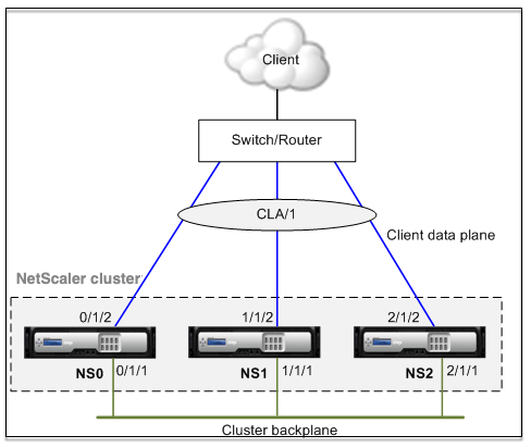
For example, consider a three-node cluster where all three nodes are connected to the upstream switch. A cluster LA channel (CLA/1) is formed by binding interfaces 0/1/2, 1/1/2, and 2/1/2.
Figure 1. Cluster Link Aggregation topology
A cluster LA channel has the following attributes:
- Each channel has a unique MAC agreed upon by cluster nodes.
- The channel can bind both local and remote nodes’ interfaces.
- A maximum of four cluster LA channels are supported in a cluster.
- Backplane interfaces cannot be part of a cluster LA channel.
- When an interface is bound to a cluster LA channel, the channel parameters have precedence over the network interface parameters. A network interface can be bound to one channel only.
- Management access to a cluster node, must not be configured on a cluster LA channel (for example, CLA/1) or its member interfaces. This is because when the node is INACTIVE, the corresponding cluster LA interface is marked as power down, and therefore looses management access.
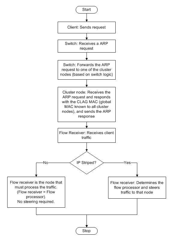
Figure 2. Traffic distribution flow using cluster LA
Backup and restore support of cluster LA on NetScaler MPX
You can backup and restore the cluster setup of LA on NetScaler MPX. The cluster LA MAC address is independent of the physical interface MAC address of the cluster nodes, and can change after the backup and restore process. The cluster LA can serve the traffic after a cluster restore process is complete. For more information about backup and restore, see Backup and restore of cluster setup