Using Citrix SD-WAN to connect to Microsoft Azure Virtual WAN
For on-premises devices to connect into Azure a controller is required. A controller ingests Azure APIs to establish site-to -site connectivity with the Azure WAN and a Hub.
Microsoft Azure Virtual WAN includes the following components and resources:
-
WAN: Represents entire network in Microsoft Azure. It contains links to all Hubs that you would like to have within this WAN. WANs are isolated from each other and cannot contain a common hub, or connections between two hubs in different WANs.
-
Site: Represents your on-premises VPN device and its settings. A Site can connect to multiple hubs. By using Citrix SD-WAN, you can have a built-in solution to automatically export this information to Azure.
-
Hub: Represents the core of your network in a specific region. The Hub contains various service endpoints to enable connectivity and other solutions to your on-premises network. Site-to-site connections are established between the Sites to a Hubs VPN endpoint.
-
Hub virtual network connection: Hub network connects the Azure Virtual WAN Hub seamlessly to your virtual network. Currently, connectivity to virtual networks that are within the same Virtual Hub Region is available.
-
Branch: The branches are the on-premises Citrix SD-WAN appliances, which exist in customer office locations. An SD-WAN controller manages the branches centrally. The connection originates from behind these branches and terminates into Azure. The SD-WAN controller is responsible for applying the required configuration to these branches and to Azure Hubs.
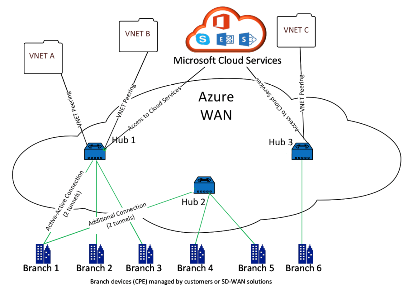
The following illustration describes the Virtual WAN components:
How does Microsoft Azure Virtual WAN work
-
The SD-WAN Center is authenticated by using service principal, principal, or role-based access functionality, which is enabled in the Azure GUI.
-
The SD-WAN Center obtains Azure connectivity configuration and updates the local device. This automates the configuration download, editing, and updating of the on-premise device.
-
After the device has the correct Azure configuration, a site-to-site connection (two active IPsec tunnels) is established to the Azure WAN. Azure requires the branch device connector to support IKEv2 settings. The BGP configuration is optional.
Note: IPsec parameters for establishing IPsec tunnels are standardized.
IPsec Property Parameter Ike Encryption Algorithm AES 256 Ike Integrity Algorithm SHA 256 Dh Group DH2 IPsec Encryption Algorithm GCM AES 256 IPsec Integrity Algorithm GCM AES 256 PFS Group None
Azure Virtual WAN automates connectivity between the workload virtual network and the hub. When you create a Hub Virtual Network Connection, it sets the appropriate configuration between the provisioned hub and the workloads virtual network (VNET).
Prerequisites and requirements
Read the following requirements before proceeding with configuring Azure and SD-WAN to manage branch sites connecting to Azure hubs.
- Have whitelisted Azure subscription for Virtual WAN.
- Have an on-premises appliance such as, an SD-WAN appliance to establish IPsec into Azure resources.
- Have Internet links with public IP addresses. Though a single Internet link is sufficient to establish connectivity into Azure, you need two IPsec tunnels to use the same WAN link.
- SD-WAN controller – a controller is the interface responsible for configuring SD-WAN appliances for connecting into Azure.
- A VNET in Azure that has at least one workload. For instance, a VM, which is hosting a service. Consider the following points:
- The virtual network should not have an Azure VPN or Express Route gateway, or a network virtual appliance.
- The virtual network should not have a user-defined route, which routes traffic to a non-Virtual WAN virtual network for the workload accessed from on-premises branch.
- Appropriate permissions to access the workload must be configured. For example, port 22 SSH access for a ubuntu VM.
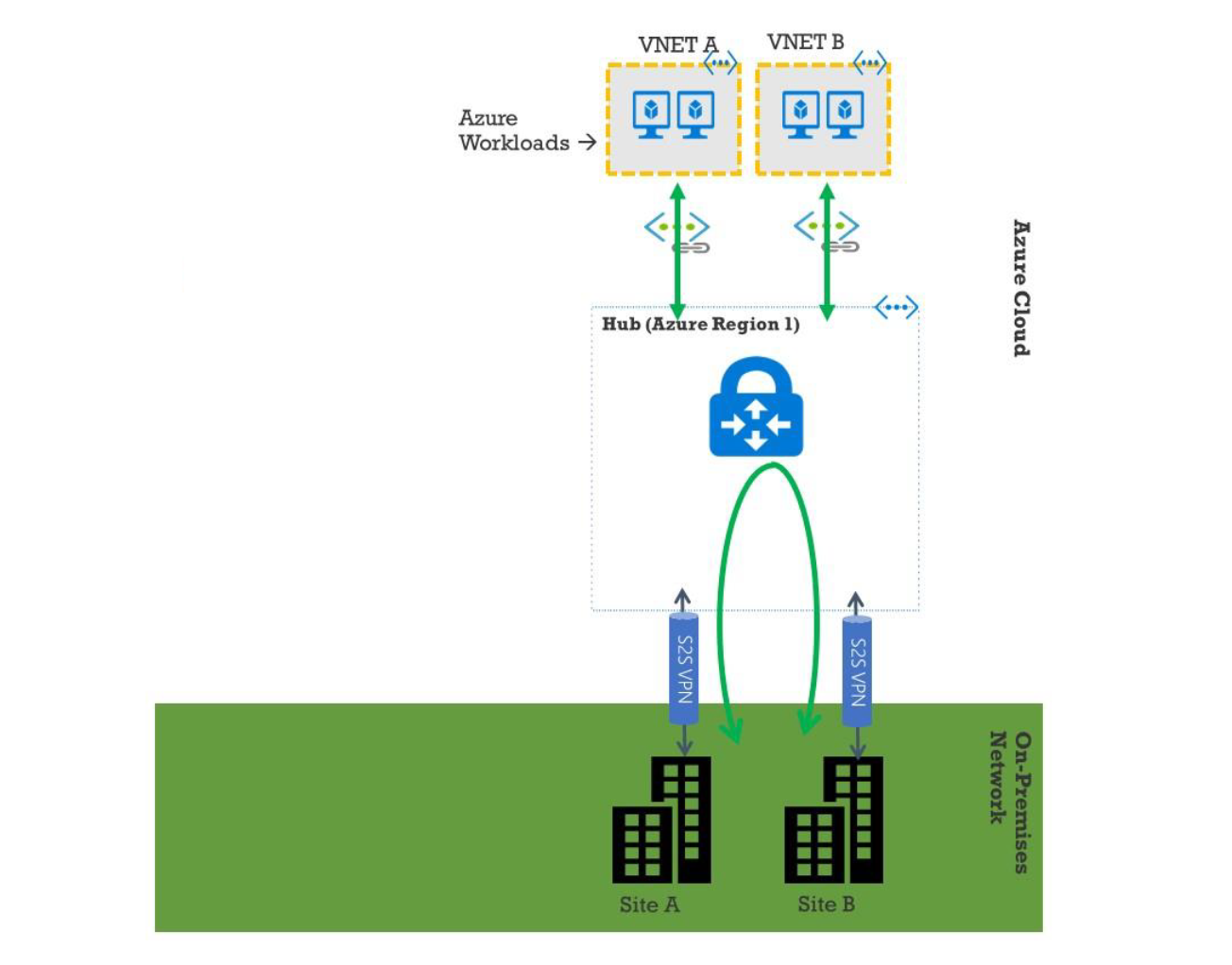
The following diagram illustrates a network with two sites and two virtual networks in Microsoft Azure.
Set up Microsoft Azure Virtual WAN
For on-premises SD-WAN branches to connect into Azure and access the resources over IPsec tunnels, the following steps should be completed.
- Configuring WAN resources.
- Enabling SD-WAN branches to connect into Azure using IPsec tunnels.
Configure Azure network before configuring SD-WAN network, since the Azure resources required to connect to SD-WAN appliances must be available beforehand. However, you can configure SD-WAN configuration before configuring Azure resources, if you prefer. This topic discusses setting up the Azure Virtual WAN network first before configuring SD-WAN appliances. https://microsoft.com azure virtual-wan.
Create a WAN resource
To use Virtual WAN features and connect the on-premises branch appliance into Azure:
-
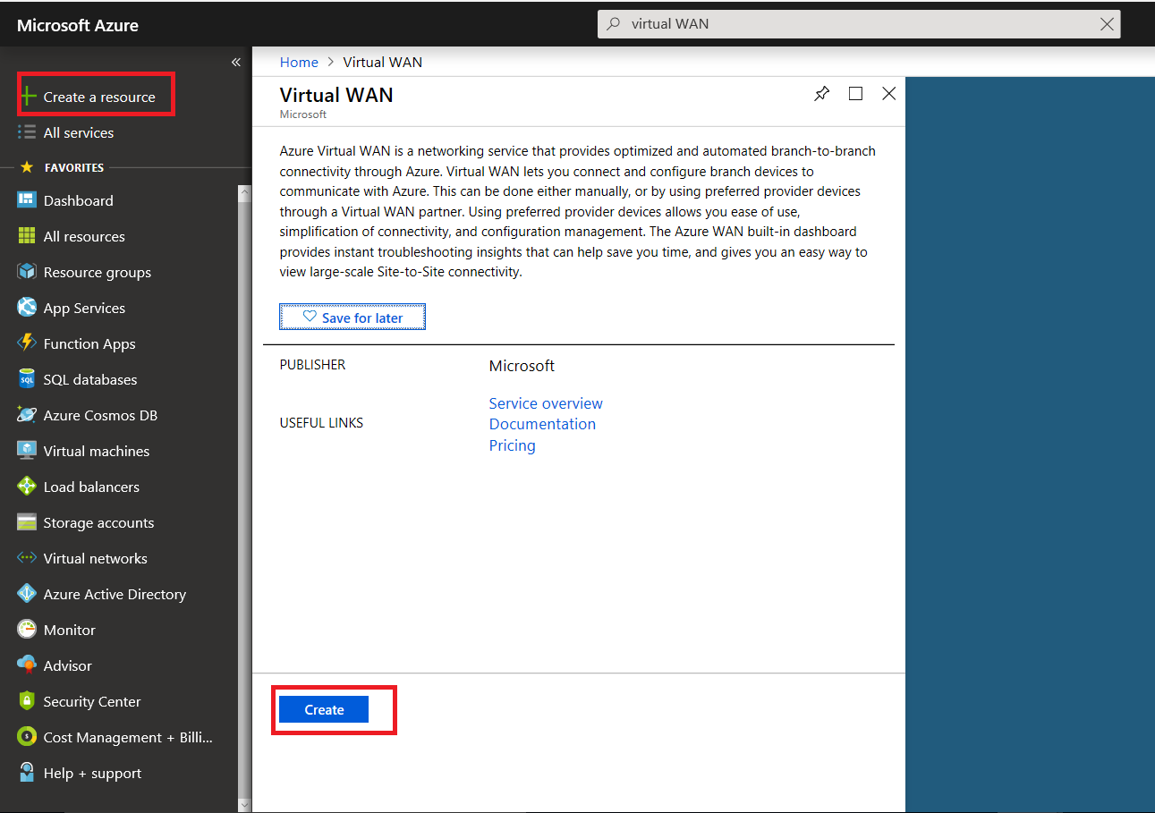
Sign in to Azure Marketplace, go to the Virtual WAN app, and select Create WAN.
-
Enter a name for the WAN and select the subscription you want to use for WAN.
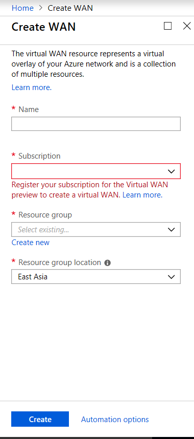
- Select an existing resource group or create a fresh resource group. Resource groups are logical constructs and data exchange across resource groups is always possible.
-
Select the location where you want your resource group to reside. WAN is a global resource that does not have a location. However, you must enter a location for the resource group that contains metadata for WAN resource.
- Click Create. This starts the process to validate and deploy your settings.
Create site
You can create a site by using a preferred vendor. The preferred vendor sends the information about your device and site to Azure or you can decide to manage the device yourself. If you want to manage the device, you need to create the site in Azure Portal.
SD-WAN network and Microsoft Azure Virtual WAN workflow
Configure SD-WAN appliance:
- Provision a Citrix SD-WAN appliance
- Connect SD-WAN branch appliance to the MCN appliance.
- Configure SD-WAN appliance
- Configure Intranet Services for Active-Active connection.
Configure SD-WAN Center:
- Configure SD-WAN Center to connect to Microsoft Azure.
Configure Azure settings:
- Provide Tenant ID, Client ID, Secure Key, Subscriber ID, and Resource Group.
Configure branch site to WAN association:
- Associate one WAN resource to a branch. Same site cannot be connected to multiple WANs.
- Click New to configure Site-WAN association.
- Select Azure Wan-resources.
- Select Services (Intranet) for the site. Select two services for Active-Standby support.
- Select Site Names to be associated with the Wan-resources.
- Click Deploy to confirm the association.
- Wait for the status to change to Tunnels Deployed to view the IPsec tunnel settings.
- Use the SD-WAN Center Reporting view to check status of the respective IPsec tunnels.
Configure Citrix SD-WAN network
MCN:
The MCN serves as the distribution point for the initial system configuration and subsequent configuration changes. There can be only one active MCN in a Virtual WAN. By default, appliances have the pre-assigned role of client. To establish an appliance as the MCN, you must first add and configure the site as an MCN. The network configuration GUI becomes available after a site is configured as an MCN. Upgrades and configuration changes must be performed from the MCN or SD-WAN center only.
Role of MCN:
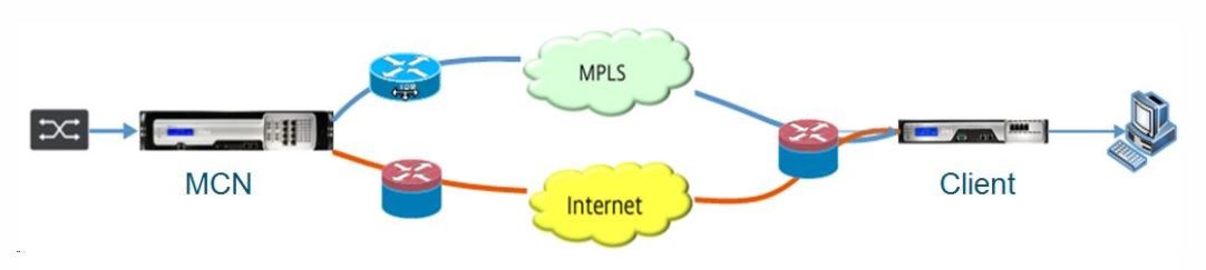
The MCN is the central node that acts as the controller of an SD-WAN network and the central administration point for the client nodes. All configuration activities, and preparation of firmware packages and their distribution to the clients, are configured on the MCN. In addition, monitoring information is available only on the MCN. The MCN can monitor the entire SD-WAN network, whereas client nodes can monitor only the local Intranets and some information for those clients, which they are connected. The primary purpose of the MCN is to establish overlay connections (virtual paths) with one or more client nodes located across the SD-WAN network for Enterprise Site-to-Site communication. An MCN can administer and have Virtual Paths to multiple client nodes. There can be more than one MCN, but only one can be active at any given time. The below figure illustrates the basic diagram of the MCN and client (branch node) appliances for a small two site network.
Configure SD-WAN appliance as MCN
To add and configure the MCN, you must first log into the Management Web Interface on the appliance you are designating as the MCN, and switch the Management Web Interface to MCN Console mode. MCN Console mode enables access to the Configuration Editor in the Management Web Interface to which you are currently connected. You can then use the Configuration Editor to add and configure the MCN site.
To switch the Management Web Interface to MCN Console mode, do the following:
- Log into the SD-WAN management web interface on the appliance you want to configure as the MCN.
- Click Configuration in the main menu bar of the Management Web Interface main screen (blue bar at the top of the page).
- In the navigation tree (left pane), open the Appliance Settings branch and click Administrator Interface.
-
Select the Miscellaneous tab. The miscellaneous administrative settings page opens.
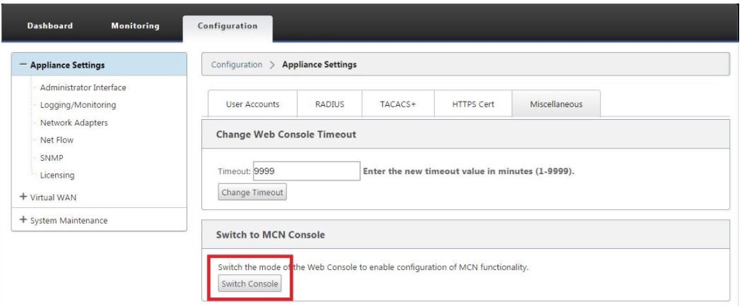
At the bottom of the Miscellaneous tab page is the Switch to [Client, MCN] Console section. This section contains the Switch Console button for toggling between appliance console modes.
The section heading indicates the current console mode, as follows:
- When in Client Console mode (default), the section heading is Switch to MCN Console.
- When in MCN Console mode, the section heading is Switch to Client Console.
By default, a new appliance is in the Client Console mode. MCN Console mode enables the Configuration Editor view in the navigation tree. The Configuration Editor is available on the MCN appliance, only.
Configure MCN
To add and begin configuring the MCN appliance site, do the following:
-
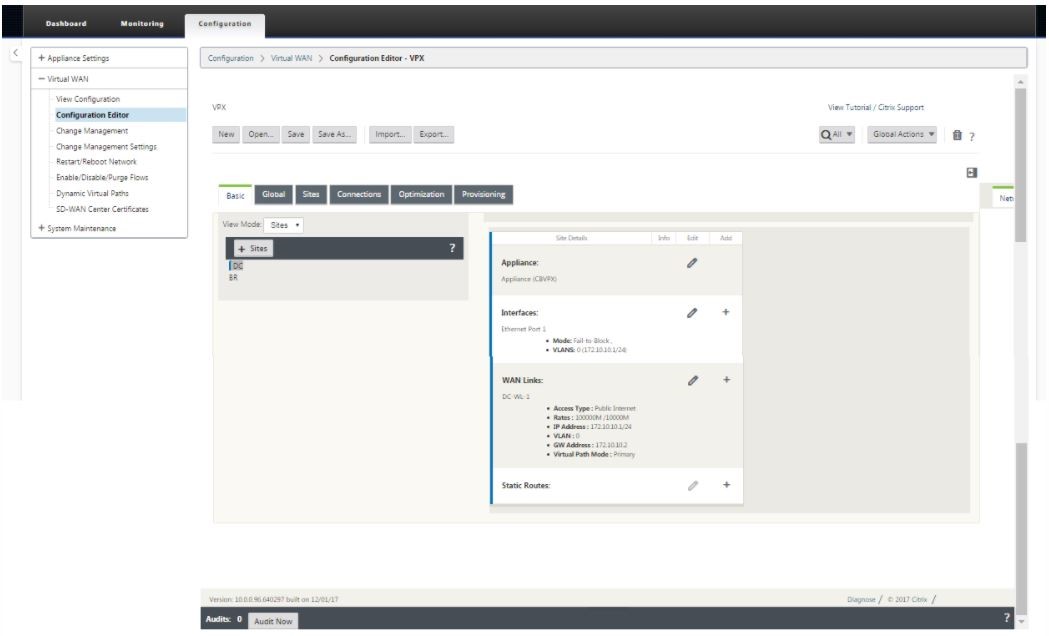
In the SD-WAN appliance GUI, navigate to Virtual WAN > Configuration Editor.
-
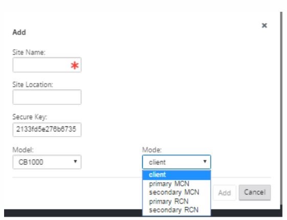
Click + Sites in the Sites bar to begin adding and configuring the MCN site. The Add Site dialog box is displayed.
-
Enter a site name that lets you determine the geographic location and role of the appliance (DC/secondary DC). Select the correct appliance model. Selecting the correct appliance is crucial since the hardware platforms differ from each other in terms of processing power and licensing. Since we are configuring this appliance as the primary head end appliance, choose the mode as primary MCN and click Add.
-
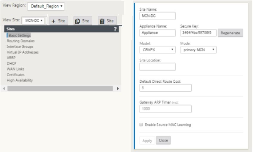
This adds the new site to the sites tree and the default view shows the basic settings configuration page as shown below:
-
Enter the basic settings such as location, site name.
- Configure the appliance so that it can accept traffic from Internet/MPLS/Broadband. Define the interfaces where the links are terminated. This depends on whether the appliance is either in overlay or underlay mode.
-
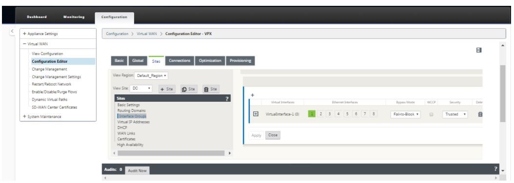
Click Interface groups to start defining the interfaces.
-
Click + to add virtual interface groups. This adds a new virtual interface group. The number of virtual interfaces depends on the links that you want the appliance to handle. The number of links that an appliance can handle varies from appliance model to model and the maximum number of links can be up to eight.
-
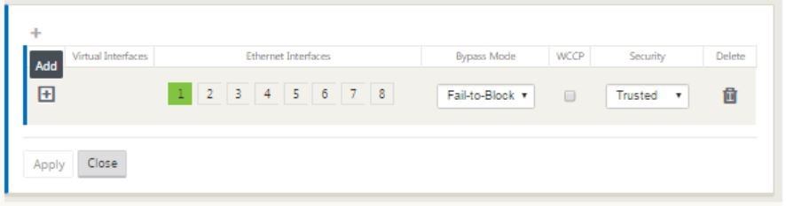
Click + to the right of virtual interfaces to view the screen as shown below.
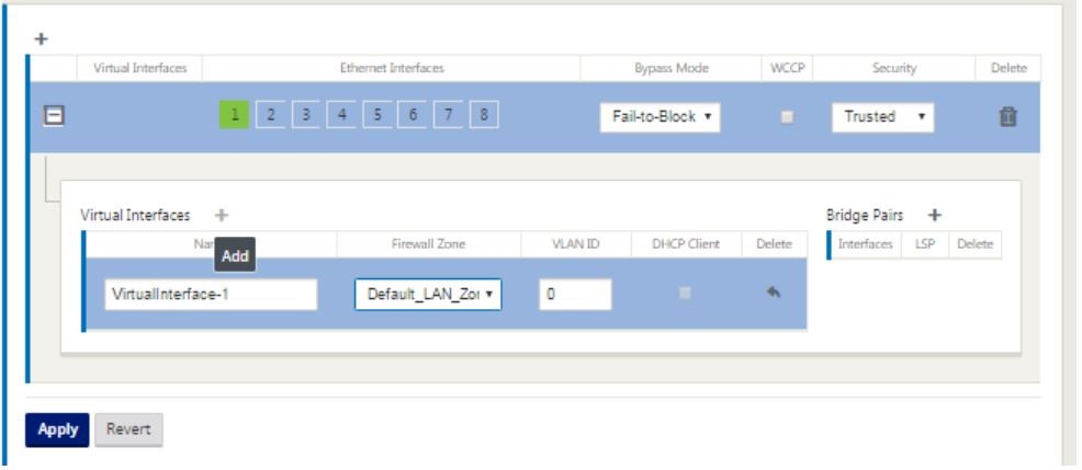
- Select the Ethernet interfaces, which form the part of this virtual interface. Depending on the platform model, appliances have a pre-configured pair of fail-to-wire interfaces. If you want to enable fail-to-wire on appliances, then ensure that you are choosing the correct pair of interfaces and ensure that you choose fail-to-wire under the Bypass Mode column.
- Select the security level from the drop-down list. Trusted mode is chosen, if the interface is serving MPLS links and Untrusted is chosen when Internet links are used on the respective interfaces.
-
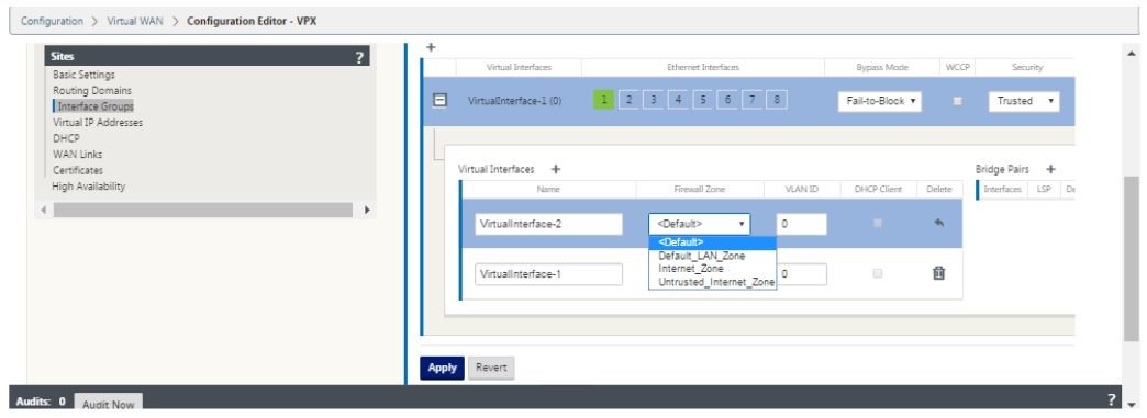
Click + to the right of the label named virtual interfaces. This shows the Name, firewall zone and VLAN IDs. Enter the Name and VLAN ID for this virtual interface group. VLAN ID is used to identifying and marking traffic to and from the virtual interface, use 0 (zero) for native/untagged traffic.
- To configure the interfaces in fail to wire, click Bridge pairs. This adds a new bridge pair and allows for editing. Click Apply to confirm these settings.
- To add more virtual interface groups click + to the right of the interface groups branch and proceed as above.
- After the interfaces are chosen, the next step is to configure IP addresses on these interfaces. In Citrix SD-WAN terminology this is known as a VIP (Virtual IP).
-
Continue in the sites view and click the Virtual IP address to view the interfaces for configuring VIP.
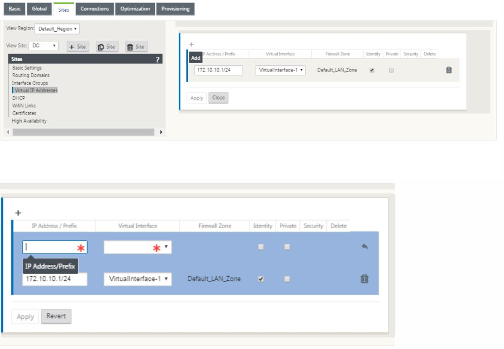
-
Enter the IP Address / Prefix information, and select the Virtual Interface with which the address is associated. The Virtual IP Address must include the full host address and netmask. Select the desired settings for the Virtual IP address, such as the Firewall Zone, Identity, Private, and Security. Click Apply. This adds the address information to the site and includes it in the site Virtual IP Addresses table. To add more Virtual IP Addresses, click + to the right of the Virtual IP Addresses, and proceed as above.
-
Continue in the sites section to configure WAN Links for the site.
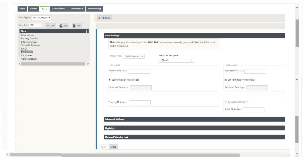
-
Click Add link, at the top of the panel on the right hand side. This opens a dialog box, which allows you to choose the type of link to be configured.
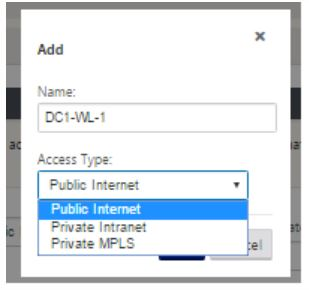
- Public Internet is for Internet/broadband/DSL/ADSL links, whereas private MPLS is for MPLS links. Private Intranet is also for MPLS links. The difference between private MPLS and private Intranet links is that private MPLS allows for preserving the QoS policies of MPLS links.
- If you are choosing public Internet and the IPs are assigned through DHCP, choose the auto detect IP option.
-
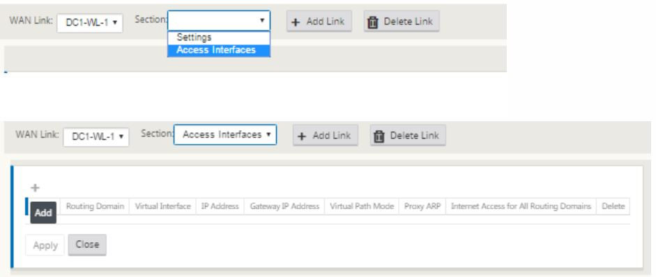
Select Access Interfaces in the WAN link configuration page. This opens the Access Interfaces view for the site. Add and configure the VIP and gateway IP for each of the links as shown below.
-
Click + to add an interface. This adds a blank entry to the table and opens it for editing.
- Enter the name you want to assign to this Interface. You may choose to name it based on the link type and location. Keep the routing domain as default if you do not want to segregate networks and assign an IP to the Interface.
-
Ensure that you provide a publicly reachable gateway IP address if the link is an internet link or a private IP if the link is an MPLS link. Keep the virtual path mode as primary since you need this link to form virtual path.
Note: Enable proxy ARP as the appliance replies to ARP requests for the gateway IP address when the gateway is unreachable.
- Click Apply to finish configuring WAN link. If you want to configure more WAN links, then repeat the steps for another link.
- Configure routes for the site. Click Connections view and select routes.
-
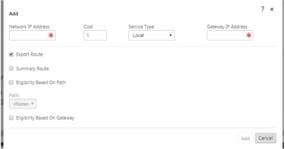
Click + to add routes, this opens a dialog box as shown below.
-
Enter the following information is available for the new route:
- Network IP Address
- Cost – Cost determines which route takes precedence over the other. Paths with lower costs take precedence over higher cost routes. The default value is five.
- Service type – Select the service, a service can be any of the following:
- Virtual Path
- Intranet
- Internet
- Passthrough
- Local
- GRE Tunnel
- LAN IPsec tunnel
- Click Apply.
To add more routes for the site click + to the right of the routes branch and proceed as above. For more information, refer to Configure MCN.
Configure virtual path between MCN and branch sites
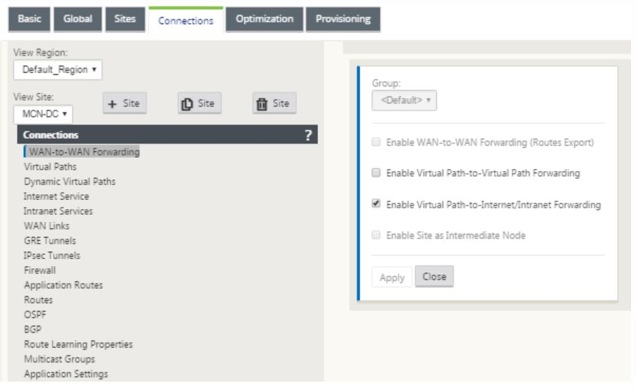
Establish connectivity between the MCN and branch node. You can do this by configuring a virtual path between these two sites. Navigate to the Connections tab in the configuration tree of the configuration editor.
- Click the Connections tab in the configuration section. This displays the connections section of configuration tree.
-
Select the MCN from view site drop-down menu in the connections section page.
-
Select virtual path from under the connections tab to create virtual path between the MCN and branch sites.
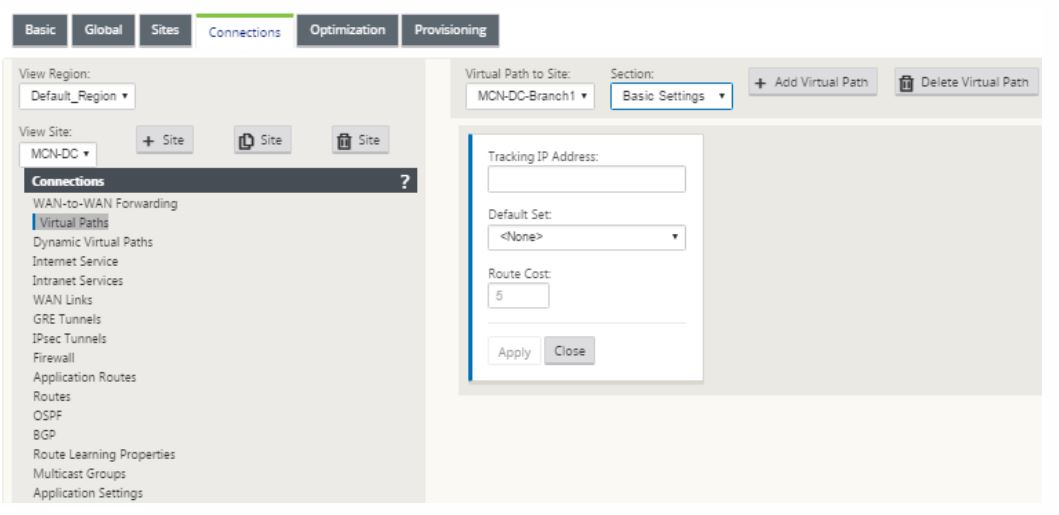
-
Click Add Virtual Path next to the name of the static virtual path in the virtual paths section. This opens up a dialog box as shown below. Choose the branch for which you want the Virtual path to be configured. You must configure this under the label named remote site. Select the branch node from this drop-down list, and click the check box Reverse Also.
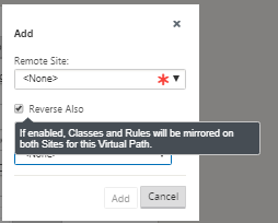
Traffic classification and steering are mirrored on both sites of the virtual path. After this is complete, select paths from the drop-down menu under the label named section as shown below.
-
Click + Add above the paths table, which displays the add path dialog box. Specify the end-points within which the virtual path must be configured. Now, click Add to create the path and click the Reverse Also checkbox.
Note: Citrix SD-WAN measures link quality in both directions. This means point A to point B is one path and point B to point A is another path. With the help of unidirectional measurement of link conditions, the SD-WAN is able to choose the best route to send traffic over. This is different from measures such as RTT, which is a bi-directional metric to measure latency. For example, one connection between point A and point B is displayed as two paths and for each of them the link performance metrics are calculated independently.
This setting is enough to bring the virtual paths up between the MCN and the branch, other configuration options are also available. For more information, refer to Configure virtual path service between MCN and Client sites.
Deploy MCN configuration
The next step is to deploy the configuration. This involves the following two steps:
-
Export the SD-WAN configuration package to Change Management.
- Before you can generate the Appliance Packages, you must first export the completed configuration package from the Configuration Editor to the global Change Management staging inbox on the MCN. Refer to the steps provided in the section, Perform change management.
-
Generate and stage the appliance packages.
- After you have added the new configuration package to the Change Management inbox, you can generate and stage the Appliance Packages on the branch sites. To do this, you use the Change Management wizard in the management web interface on the MCN. Refer to the steps provided in the section, Stage Appliance Packages.
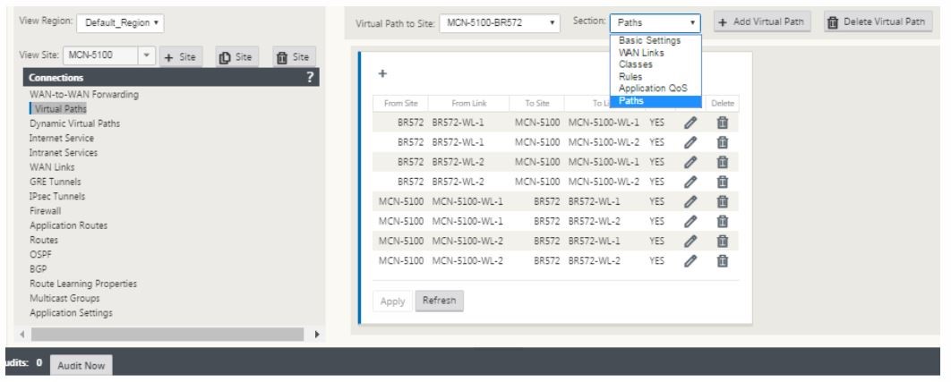
Configure intranet services to connect with Azure WAN resources
-
In the SD-WAN appliance GUI, go to the Configuration Editor. Navigate to the Connections tile. Click + Add Service to add an Intranet Service for that site.
-
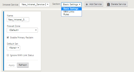
In the Basic Settings for the Intranet Service, there are several options on how you want the Intranet Service to behave during unavailability of WAN links.
- Enable primary reclaim – check this box if you want the chosen primary link to take over when it comes up after failing over. If you however, choose not to check this option then the secondary link would continue to send traffic over.
-
Ignore WAN Link status – If this option is enabled, then packets destined for this intranet service would continue to use this service even if the constituent WAN links are unavailable.
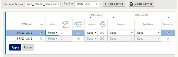
-
After configuring the basic settings, the next step is to choose the constituent WAN Links for this service. At the maximum of two links are chosen for one Intranet service. To choose the WAN links please select the WAN links option from the drop-down list labeled Section. The WAN links function in primary and secondary mode and only one link are chosen as a primary WAN link.
Note: When a second intranet service is created, it must have the primary and secondary wan-link mapping.
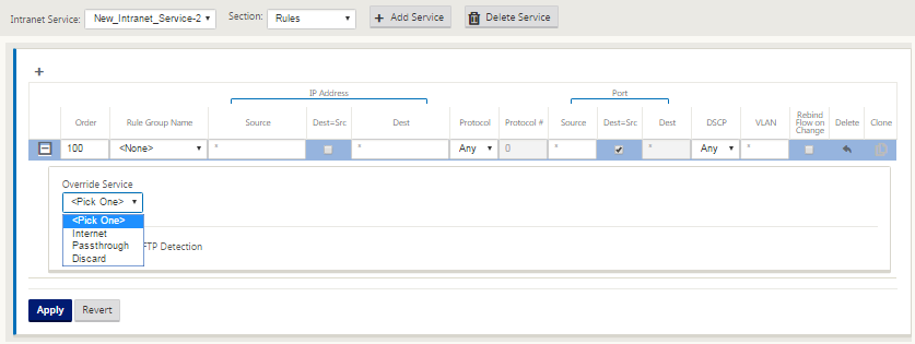
-
Branch site specific Rules are available, enabling the capability of customization of each branch site uniquely overriding any general settings configured in the global default set. Modes include desired delivery over a specific WAN link, or as an Override Service allowing for pass through or discard of the filtered traffic. For instance, if there is some traffic, which you do not want to be going over the intranet service, you can write a rule to discard that traffic or send it over a different service (internet or pass through).
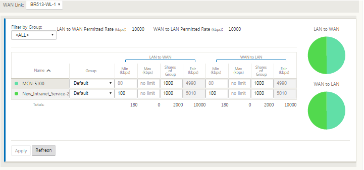
-
With Intranet Service enabled for a site, the Provisioning tile is made available to allow for the bidirectional (LAN to WAN / WAN to LAN) distribution of bandwidth for a WAN link among the various services using the WAN link. The Services section allows you to further fine-tune bandwidth allocation. In addition, fair share can be enabled, allowing services to receive their minimum reserved bandwidth before fair distribution is enacted.
Configure SD-WAN Center
The following diagram describes the high-level workflow of SD-WAN Center and Azure Virtual WAN connection.
Configure Azure settings:
- Provide Tenant ID, Client ID, Secure Key, Subscriber ID, and Resource Group.
Configure branch site to WAN association:
- Associate one WAN resource to a branch sites. Same site cannot be connected to multiple WANs.
- Click New to configure Site-WAN association.
- Select Azure Wan-resources.
- Select Services (Intranet) for the site. Two services should be selected for Active-Standby support.
- Select Site Names to be associated with the Wan-resources.
- Click Deploy to confirm the association.
- Wait for the status to change to ‘Downloaded’ to view the IPsec tunnel settings.
- Use the SD-WAN Center Reporting view to check status of the respective IPsec tunnels. The IPsec tunnel status should be GREEN for the data traffic to flow.
Provision SD-WAN Center:
SD-WAN center is the management and reporting tool for Citrix SD-WAN. The required configuration for Virtual WAN is performed in SD-WAN Center. SD-WAN center is available only as a virtual form factor (VPX) and needs to be installed on a VMware ESXi or a XenServer hypervisor. The minimum resources needed to configure an SD-WAN center appliance are 8 GB RAM and 4 CPU cores. Here are the steps to Install and configure an SD-WAN center VM.
Configure SD-WAN Center for Azure connectivity
Ensure that intranet services for the required sites are configured and the service policy information of the Azure portal is configured in the SDWAN center. See instructions provided in the section above. Before using SD-WAN center to connect with Azure WAN resources, you need to create a service principal used to authenticate a third party application (SD-WAN center in this case) with Azure. Read create a service principal for more information.
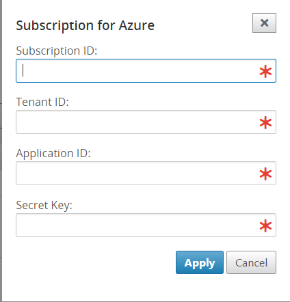
To successfully authenticate SD-WAN center with Azure, the following parameters should be available:
- Tenant ID
- Client ID
- Secure Key
- Subscriber ID
Ensure that intranet services for the required sites are configured and the service policy information of the Azure portal is configured in the SDWAN center. See instructions provided in the section above.
Authenticate SD-WAN Center:
In the SD-WAN Center UI, navigate to Configuration > Cloud Connectivity. Configure Azure connection settings. Refer to the following link for more information about configuring Azure VPN connection, Azure Resource Manager.
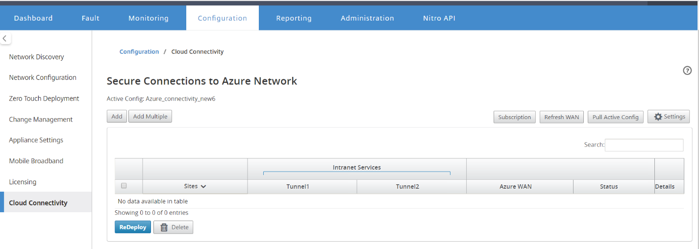
Enter the Tenant ID, Secure Key, Subscriber ID, and Application ID. This step is required to authenticate SD-WAN center with Azure. If the credentials entered above are not correct, then the authentication fails and further action is not allowed. Click Apply.
The Storage account field refers to the storage account that you have created in Azure. If you did not create a storage account then a new storage account is automatically created in your subscription when you click Apply.
Obtain Azure Virtual WAN resources:
After authentication is successful, Citrix SD-WAN polls Azure for obtaining a list of Azure virtual WAN resources, which you created in the first step after logging into Azure portal. The WAN resources are the endpoints or hubs for terminating the IPsec tunnels initiated from the branch sites. This resource represents your entire network in Azure. It contains links to all Hubs that you would like to have within this WAN. WANs are isolated from each other and cannot contain a common hub or connections between two different hubs in different WAN resources.
To associate branch sites and Azure WAN resources:
A branch site needs to be associated with Azure WAN resources to establish IPsec tunnels. One branch can be connected to multiple such Azure virtual WAN resources and one Azure virtual WAN resource can be connected with multiple on-premises branch sites.
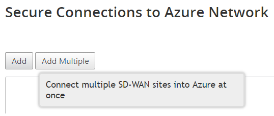
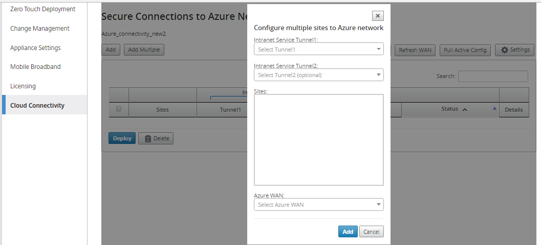
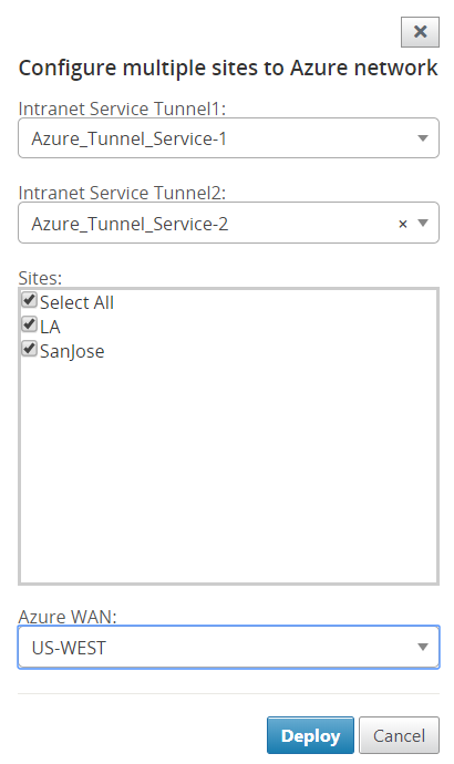
To add multiple sites:
You can choose to add multiple sites at once and associate them to an Azure WAN resource.
-
Click Add Multiple to add all the sites with same set of services and associate them with the chosen WAN resources.
-
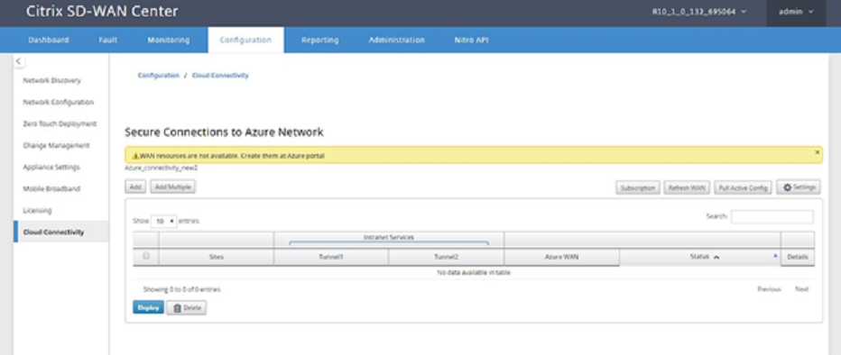
The Azure WAN resources drop-down list (shown below) is pre-populated with the resources belonging to your Azure account. If no WAN resources have been created then this list is empty, and you must navigate to the Azure portal to create the resources. If the list is populated with WAN resources, choose the Azure WAN resource to which you need the branch sites to be connected to.
-
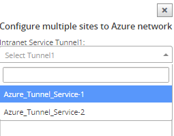
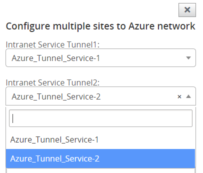
Select the Intranet service created, you can select two Intranet services in this field. Services correspond to the Intranet services you created using SD-WAN configuration.
-
Choose one or all of the branch sites to initiate the process of IPsec tunnel establishment. Based on the Intranet services selected, the available branch information is populated. All branches with required services are displayed.
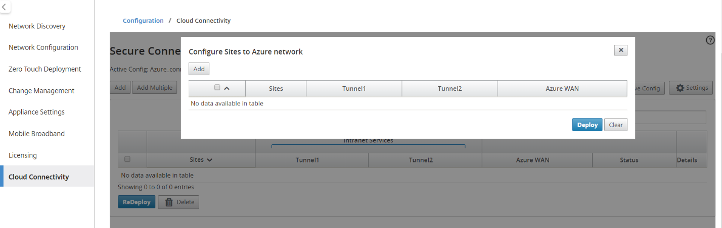
To add single site:
You can also choose to add sites one-by-one (single) and as your network grows, or if you are performing a site-by-site deployment, you can choose to add multiple sites as described above.
-
Click Add New Entry to select one Site Name for the Site-Wan association. Add sites in the Configure Sites to Azure Network dialog box.
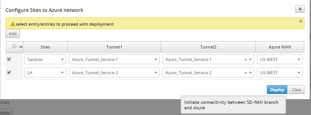
-
The Intranet services you created using the SD-WAN configuration are populated based for the selected site under Intranet Services (Tunnel1 and Tunnel2). Choose one or two Intranet services.
-
Select the wan-resource to which the site must be associated to from the Azure Virtual WANs drop-down menu.
-
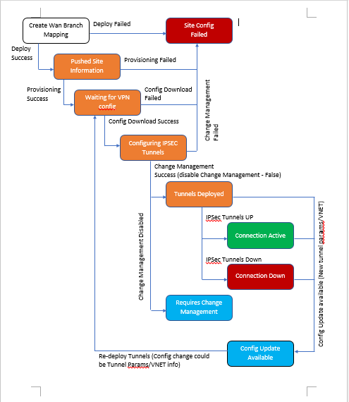
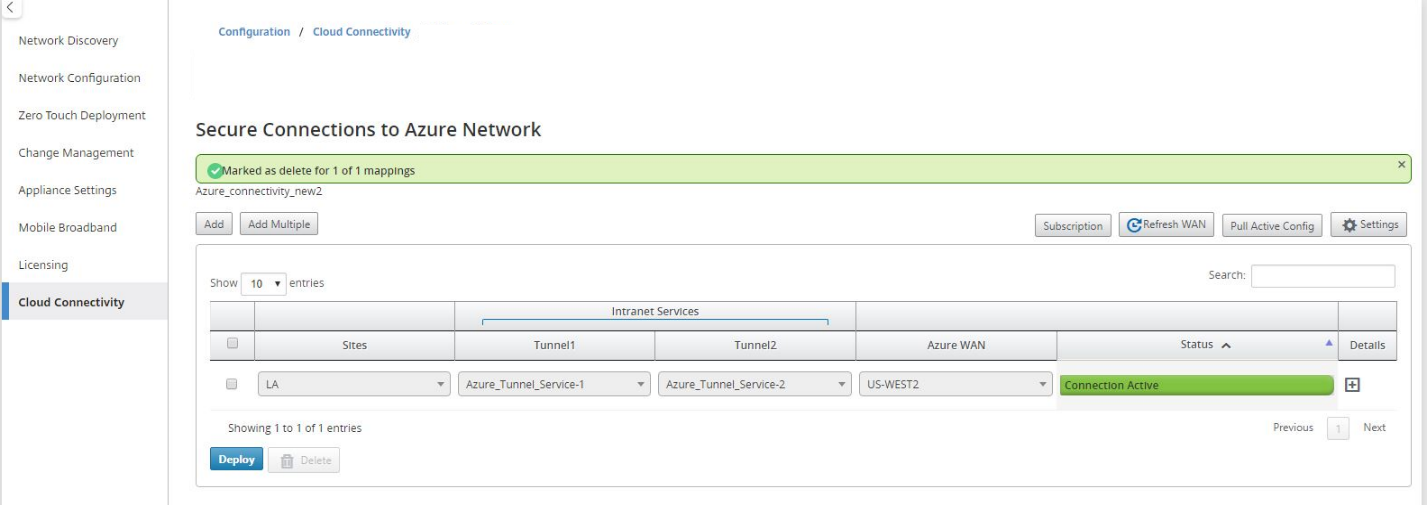
Click Deploy to confirm the association. The status (“Not pushed,” “Pushed” & “Downloaded”) is updated to notify you about the process.
The deploy process includes the following status:
- Push Site Information
- Waiting for VPN configuration
- Tunnels Deployed
-
Connection Active (IPsec Tunnel is up) or Connection Down (IPsec Tunnel is down)
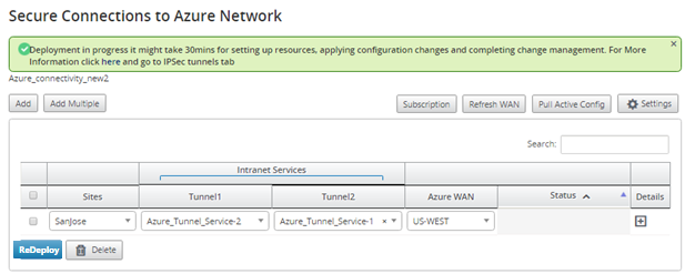
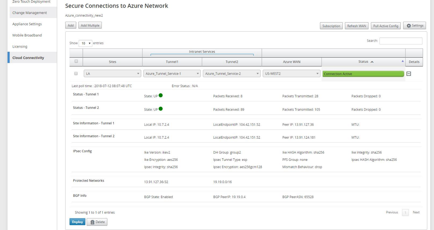
Wait for the Status to change to Connection Active to view the IPsec tunnel settings. View IPsec settings associated with the selected services.
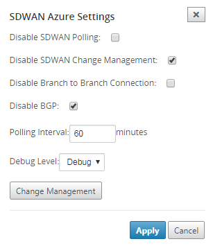
SD-WAN Azure settings:
By default, the Change Management process is automated. This means that anytime a new configuration is available at Azure Virtual WAN infrastructure, SD-WAN Center obtains it and starts applying it to branches automatically. However, this behavior is controlled, if you want to control when a configuration needs to be applied to branches. One benefit of disabling automatic change management is that the configuration for this feature and other SD-WAN features is managed independently. Polling interval option controls the interval of looking for configuration updates in Azure Virtual WAN infrastructure, the recommended time for polling interval is 2 minutes.
-
Disable Branch-to-Branch Connection – Disables branch-to-branch communication over Azure Virtual WAN infrastructure. By default, this option is disabled. Once you enable this, it means that on-prem branches are able to communicate with each other and the resources behind the branches over IPsec through Azure’s Virtual WAN Infra. This does not have any effect on branch-to-branch communication over SD-WAN virtual path, branches are able to communicate with each other and their respective resources/end points over virtual path even if this option is disabled.
-
Debug Level – Enables capturing logs to debug if there is any connectivity issues.
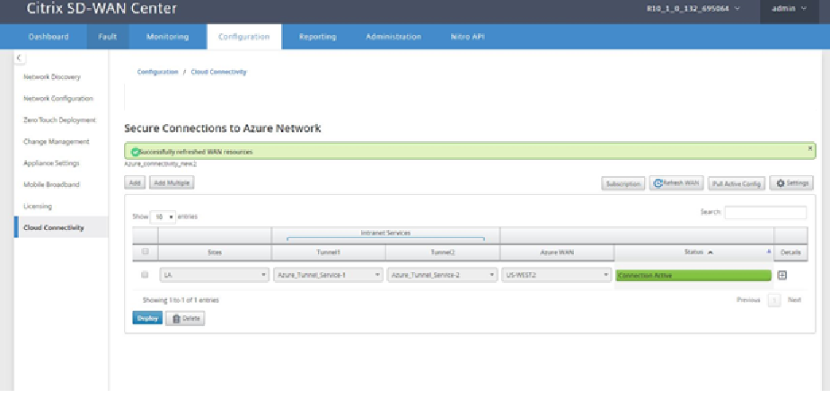
Refresh WAN resources:
Click the Refresh icon to retrieve latest set of WAN Resources that you updated on the Azure Portal. A message stating, “successfully refreshed WAN resources” is displayed after the refresh process is complete.
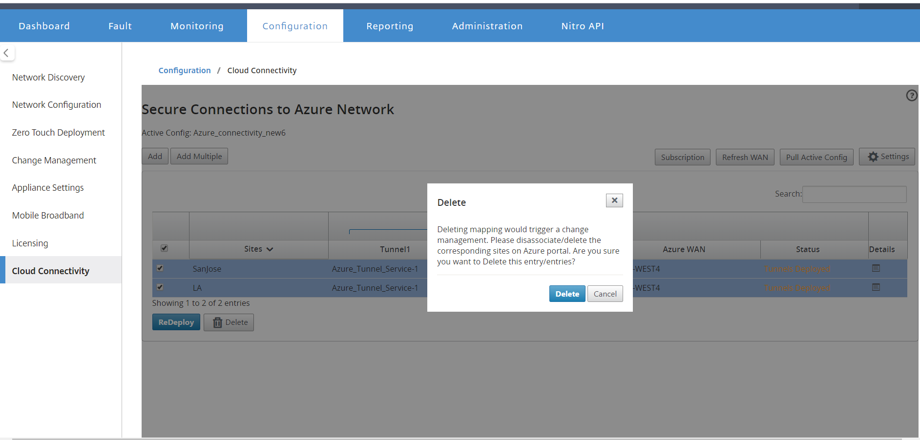
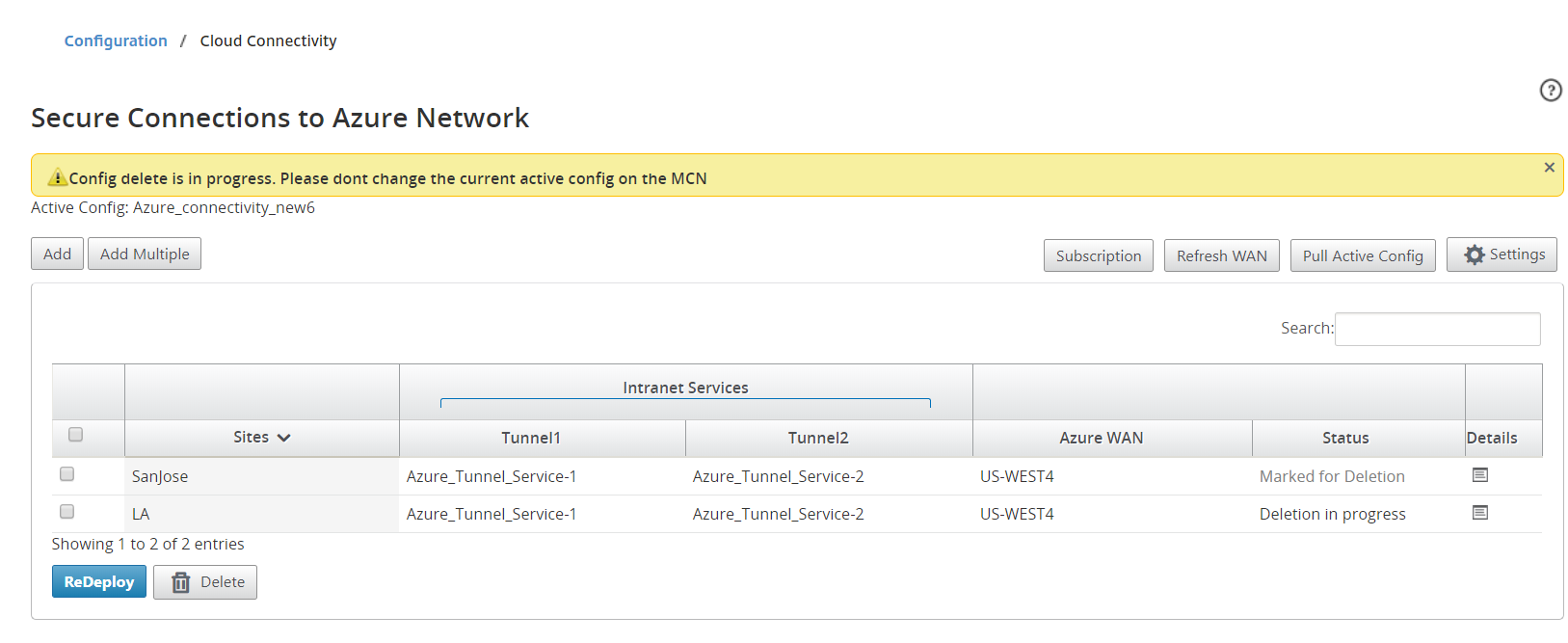
Remove site-wan resource association
Select one or multiple mappings to perform deletion. Internally, the SD-WAN appliance Change Management process is triggered and until it is successful, the Delete option is disabled to prevent from performing further deletions. Deleting mapping requires you to disassociate or delete the corresponding sites in the Azure portal.
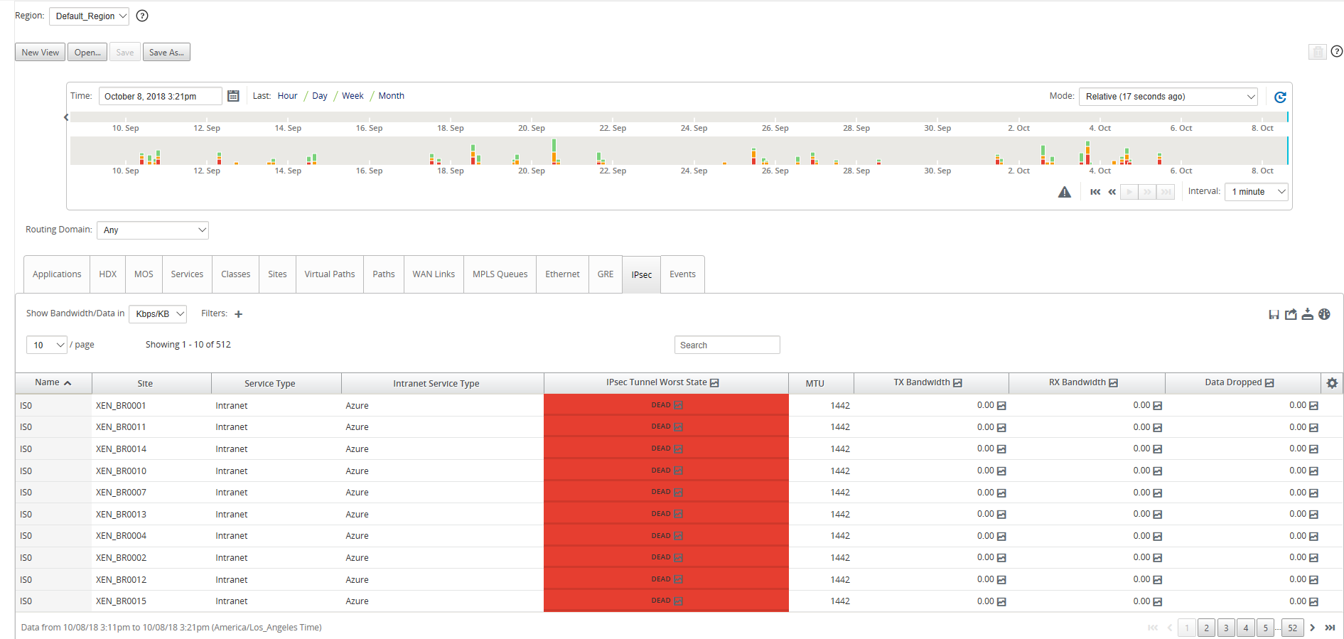
Monitor IPsec Tunnels
Navigate to the SD-WAN Center Reporting view to check status of the respective IPsec tunnels. The tunnel status should be GREEN for the data traffic to flow.