Service definitions
Delivery Channels are broadly categorized into Services Definitions and Bandwidth Allocation.
Delivery services are delivery mechanisms available on Citrix SD-WAN to steer different applications or traffic profiles using the right delivery methods based on the business intent. You can configure delivery services such as the Internet, Intranet, Virtual Paths, IPsec, and LAN GRE. The delivery services are defined globally and are applied to WAN links at individual sites, as applicable.
Each WAN link can apply all or a subset of the relevant services, and setup relative shares of bandwidth (%) among all the delivery services.
Virtual Path service is available on all the links by default. The other services can be added as needed. To configure Delivery Services, at the customer level, navigate to Configuration > Delivery Channels > Service Definitions.
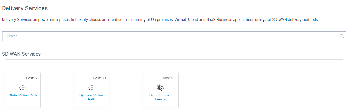
Delivery Services can be broadly categorized as the following:
-
Virtual Path Service: The dual-ended overlay SD-WAN tunnel that offers secure, reliable, and high-quality connectivity between two sites hosting SD-WAN appliances or virtual instances. Set the minimum reserved bandwidth for each virtual path in Kbps. This setting is applied to all the WAN links across all sites in the network.
- Internet Service: Direct channel between an SD-WAN site and public Internet, with no SD-WAN encapsulation involved. Citrix SD-WAN supports session load-balancing capability for Internet-bound traffic across multiple Internet links.
- Intranet Service: Underlay link based connectivity from an SD-WAN site to any non-SD-WAN site. The traffic is unencapsulated or can use any non-virtual path encapsulation such as IPsec, GRE. You can set up multiple Intranet services.
Internet service
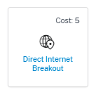
Internet Service is available by default as part of the Delivery services. To configure an Internet service, from the customer level, navigate to Configuration > Delivery Channels > Service Definitions. In the SD-WAN Services section, select the Direct Internet Breakout tile and then click Add.
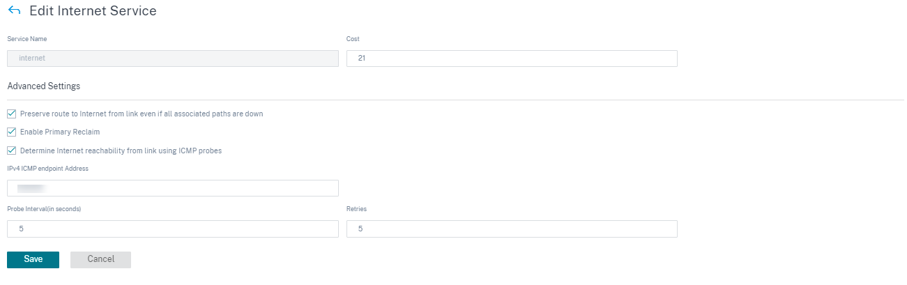
You can configure the following Internet services:
- Preserve route to Internet from link even if all associated paths are down: You can configure the Internet service route cost relative to other delivery services. With this service, you can preserve the route to the Internet from the link even if all the associated paths are down. If all paths associated with a WAN link are dead, then the SD-WAN appliance uses this route to send/receive Internet traffic.
- Determine Internet reachability from link using ICMP probes: You can enable ICMP probes for specific Internet WAN links to an explicit server on the Internet. With the ICMP probe setting, the SD-WAN appliance treats the Internet link as up when either the link’s member paths are up or when the ICMP probe response is received from the server.
- IPv4 ICMP endpoint address: The destination IPv4 address or the server address.
- Probe interval (in seconds): Time interval at which the SD-WAN appliance sends probes on the Internet configured WAN links. By default, the SD-WAN appliance sends probes on the configured WAN links every 5 seconds.
- Retries: Number of retries that you can attempt before determining whether the WAN link is up or not. After 3 consecutive probe failures, the WAN link is considered dead. Maximum retries allowed are 10.
Supported deployment modes
Internet service can be utilized in the following deployment modes:
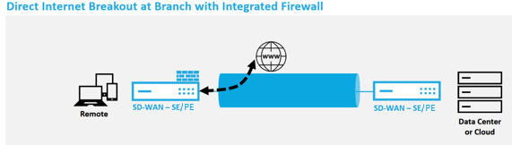
- Inline Deployment Mode (SD-WAN Overlay)
Citrix SD-WAN can be deployed as an overlay solution in any network. As an overlay solution, SD-WAN generally is deployed behind existing edge routers and/or firewalls. If SD-WAN is deployed behind a network firewall, the interface can be configured as trusted and Internet traffic can be delivered to the firewall as an Internet gateway.
- Edge or Gateway Mode
Citrix SD-WAN can be deployed as the edge device, replacing existing edge router and/or firewall devices. Onboard firewall feature allows SD-WAN to protect the network from direct internet connectivity. In this mode, the interface connected to the public internet link is configured as untrusted, forcing encryption to be enabled, and firewall and Dynamic NAT features are enabled to secure the network.
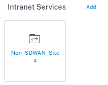
Intranet service
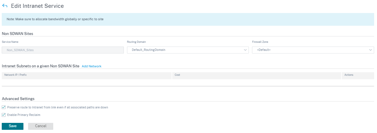
You can create multiple intranet services. To add an Intranet service, from the customer level, navigate to Configuration > Delivery Channels > Service Definitions. In the Intranet Services section, click Add.
Once the intranet service is created at the global level, you can reference it at the WAN Link level. Provide a Service Name, select the desired Routing Domain and Firewall Zone. Add all the intranet IP addresses across the network, that other sites in the network might interact. You can also preserve the route to intranet from the link even if all the associated paths are down.
GRE service
You can configure SD-WAN appliances to terminate GRE tunnels on the LAN.
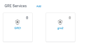
To add a GRE service, from the customer level, navigate to Configuration > Delivery Channels > Service Definitions. You can also navigate to GRE services configuration page from Configuration > Security.
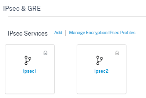
In the IPsec & GRE section, navigate to IPsec Services and click Add.
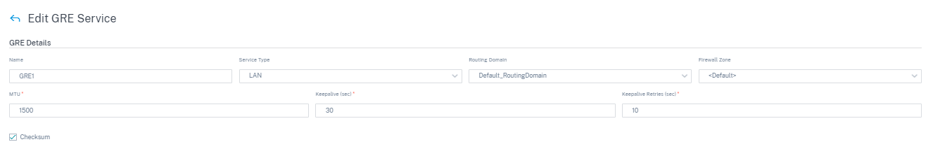
GRE details:
- Service Type: Select the service that the GRE tunnel uses.
- Name: Name of the LAN GRE service.
- Routing Domain: The routing domain for the GRE tunnel.
- Firewall Zone: The firewall zone chosen for the tunnel. By default, the tunnel is placed into the Default_LAN_Zone.
- MTU: Maximum transmission unit — the size of the largest IP datagram that can be transferred through a specific link. The range is from 576 to 1500. Default value is 1500.
- Keep alive: The period between sending keep alive messages. If configured to 0, no keep alive packets is sent, but the tunnel stays up.
- Keep alive Retries: The number of times that the Citrix SD-WAN Appliance sends keep alive packets without a response before it brings the tunnel-down.
- Checksum: Enable or disable Checksum for the tunnel’s GRE header.
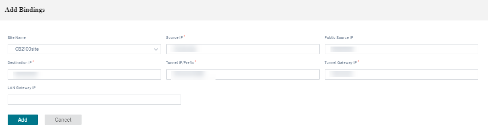
Site bindings:
- Site Name: The site to map the GRE tunnel.
- Source IP: The source IP address of the tunnel. This is one of the Virtual Interfaces configured at this site. The selected routing domain determines the available Source IP addresses.
- Public Source IP: The source IP if the tunnel traffic is going through NAT.
- Destination IP: The destination IP address of the tunnel.
- Tunnel IP/Prefix: The IP address and Prefix of the GRE Tunnel.
- Tunnel Gateway IP: The next hop IP Address to route the Tunnel traffic.
- LAN Gateway IP: The next hop IP Address to route the LAN traffic.
IPsec service
Citrix SD-WAN appliances can negotiate fixed IPsec tunnels with third-party peers on the LAN or WAN side. You can define the tunnel end-points and map the sites to the tunnel end-points.
You can also select and apply an IPsec security profile that define the security protocol and IPsec settings.
To configure Virtual Path IPsec Settings:
- Enable Virtual Path IPsec Tunnels for all Virtual Paths where FIPS compliance is required.
- Configure message authentication by changing the IPsec Mode to AH or ESP+Auth and use a FIPS approved hashing function. SHA1 is accepted by FIPS, but SHA256 is highly recommended.
- IPsec lifetime should be configured for no more than 8 hours (28,800 seconds).
Citrix SD-WAN uses IKE version 2 with pre-shared-keys to negotiate IPsec tunnels through the Virtual Path using the following settings:
- DH Group 19: ECP256 (256-bit Elliptic Curve) for key negotiation
- 256-bit AES-CBC Encryption
- SHA256 hashing for message authentication
- SHA256 hashing for message integrity
- DH Group 2: MODP-1024 for Perfect Forward Secrecy
To configure IPsec Tunnel for a third party:
- Configure FIPS approved DH Group. Groups 2 and 5 are permissible under FIPS, however groups 14 and above are highly recommended.
- Configure FIPS approved hash function. SHA1 is accepted by FIPS, however SHA256 is highly recommended.
- If using IKEv2, configure a FIPS approved integrity function. SHA1 is accepted by FIPS, however SHA256 is highly recommended.
- Configure an IKE lifetime, and max lifetime, of no more than 24 hours (86,400 seconds).
- Configure IPsec message authentication by changing the IPsec Mode to AH or ESP+Auth and use a FIPS approved hashing function. SHA1 is accepted by FIPS, but SHA256 is highly recommended.
- Configure an IPsec lifetime, and max lifetime, of no more than eight hours (28,800 seconds).
Configuring an IPsec tunnel
From the customer level, navigate to Configuration > Delivery Channels > Service Definitions. You can also navigate to IPsec services page from Configuration > Security.
In the IPsec & GRE > IPsec Services section, click Add. The Edit IPsec Service page is displayed.
-
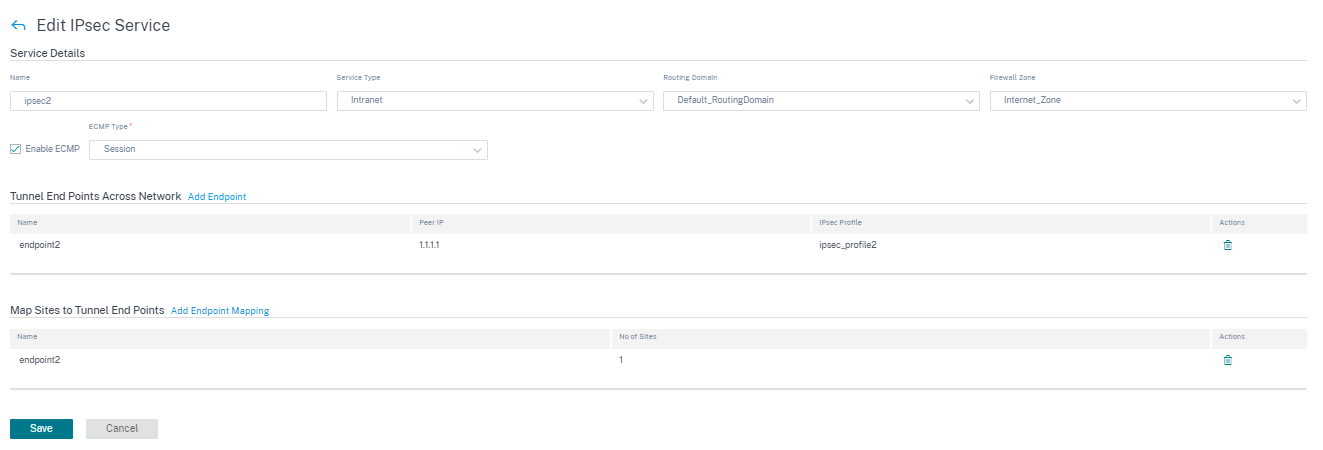
Specify the service details.
- Service Name: The name of the IPsec service.
- Service Type: Select the service that the IPsec tunnel uses.
- Routing Domain: For IPsec tunnels over LAN, select a routing domain. If the IPsec Tunnel uses an intranet service, the intranet service determines the routing domain.
- Firewall Zone: The firewall zone for the Tunnel. By default, the Tunnel is placed into the Default_LAN_Zone.
- Enable ECMP: When the Enable ECMP check box is selected, ECMP load balancing is enabled for the IPsec tunnel.
- ECMP Type: Select the type of ECMP load balancing mechanism as required. For more details about ECMP types, see ECMP load balancing.
-
Add the tunnel end-point.
- Name: When Service Type is Intranet, choose an Intranet Service the tunnel protects. Otherwise, enter a name for the service.
- Peer IP: The IP address of the remote peer.
- IPsec Profile: IPsec security profile that define the security protocol and IPsec settings.
- Pre Shared Key: The pre-shared key used for IKE authentication.
- Peer Pre Shared Key: The pre-shared key used for IKEv2 authentication.
- Identity Data: The data to be used as the local identity, when using manual identity or User FQDN type.
- Peer Identity Data: The data to be used as the peer identity, when using manual identity or User FQDN type.
- Certificate: If you choose Certificate as the IKE authentication, choose from the configured certificates.
-
Map sites to the tunnel end-points.
- Choose Endpoint: The end-point to be mapped to a site.
- Site Name: The site to be mapped to the end-point.
- Virtual Interface Name: The virtual interface at the site to be used as the end-point.
- Local IP: The local virtual IP address to use as the local tunnel end-point.
- Gateway IP: The next hop IP address.
-
Create the protected network.
- Source Network IP/Prefix: The source IP address and Prefix of the network traffic that the IPsec tunnel protects.
- Destination Network IP/Prefix: The destination IP address and Prefix of the network traffic that the IPsec tunnel protects.
-
Ensure that the IPsec configurations are mirrored on the peer appliance.
For more information about FIPS compliance, see Network security.
Note
Citrix SD-WAN Orchestrator for On-premises supports connectivity to Oracle Cloud Infrastructure (OCI) through IPsec.
IPsec encryption profiles
To add an IPsec encryption profile, at the customer level, navigate to Configuration > Delivery Channels > Service Definitions. You can also navigate to IPsec encryption profiles configuration page from Configuration > Security.
In the IPsec & GRE section, select Manage Encryption IPSec Profiles.
IPsec provides secure tunnels. Citrix SD-WAN supports IPsec virtual paths, enabling third-party devices to terminate IPsec VPN Tunnels on the LAN or WAN side of a Citrix SD-WAN appliance. You can secure site-to-site IPsec Tunnels terminating on an SD-WAN appliance by using a 140-2 Level 1 FIPS certified IPsec cryptographic binary.
Citrix SD-WAN also supports resilient IPsec tunneling using a differentiated virtual path tunneling mechanism.
IPsec profiles are used while configuring IPsec services as delivery service sets. In the IPsec security profile page, enter the required values for the following IPsec Encryption Profile, IKE Settings, and IPsec Settings.
Click Verify Configuration to validate any audit error.
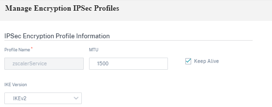
IPsec encryption profile information:
- Profile Name: Provide a profile name.
- MTU: Enter the maximum IKE or IPsec packet size in bytes.
- Keep Alive: Select the check box to keep the tunnel active and enable route eligibility.
-
IKE Version: Select an IKE protocol version from the drop-down list.
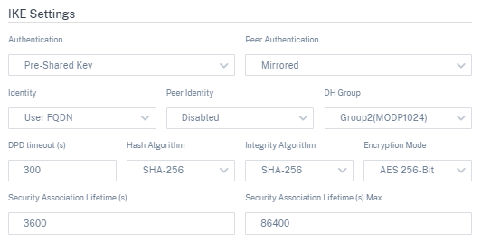
IKE settings
-
Mode: Select either Main mode or Aggressive mode from the drop-down list for the IKE Phase 1 negotiation mode.
- Main: No information is exposed to potential attackers during negotiation, but is slower than Aggressive mode. Main mode is FIPS compliant.
- Aggressive: Some information (for example, the identity of the negotiating peers) is exposed to potential attackers during negotiation, but is faster than Main mode. Aggressive mode is Non-FIPS compliant.
- Authentication: Choose the authentication type as Certificate or Pre-shared Key from the drop-down menu.
- Peer Authentication: Choose the peer authentication type from the drop-down list.
- Identity: Select the identity method from the drop-down list.
- Peer Identity: Select the peer identity method from the drop-down list.
- DH Group: Select the Diffie-Hellman (DH) group that are available for IKE key generation.
- DPD timeout (s): Enter the Dead Peer Detection timeout (in seconds) for VPN connections.
- Hash Algorithm: Choose a hashing algorithm from the drop-down list to authenticate IKE messages.
- Integrity Algorithm: Choose the IKEv2 hashing algorithm to use for HMAC verification.
- Encryption Mode: Choose the Encryption Mode for IKE messages from the drop-down list.
- Security Association Lifetime (s): Enter the amount of time, in seconds, for an IKE security association to exist.
- Security Association Lifetime (s) Max: Enter the maximum amount of time, in seconds, to allow an IKE security association to exist.
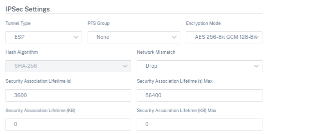
IPsec settings
-
Tunnel Type: Choose ESP, ESP+Auth, ESP+NULL, or AH as the tunnel encapsulation type from the drop-down list. These are grouped under FIPS compliant and Non-FIPS compliant categories.
- ESP: Encrypts the user data only
- ESP+Auth: Encrypts the user data and includes an HMAC
- ESP+NULL: Packets are authenticated but not encrypted
- AH: Only includes an HMAC
- PFS Group: Choose the Diffie-Hellman group to use for perfect forward secrecy key generation from the drop-down menu.
- Encryption Mode: Choose the Encryption Mode for IPsec messages from the drop-down menu.
- Hash Algorithm: The MD5, SHA1, and SHA-256 hashing algorithms are available for HMAC verification.
- Network Mismatch: Choose an action to take if a packet does not match the IPsec Tunnel’s Protected Networks from the drop-down menu.
- Security Association Lifetime (s): Enter the amount of time (in seconds) for an IPsec security association to exist.
- Security Association Lifetime (s) Max: Enter the maximum amount of time (in seconds) to allow an IPsec security association to exist.
- Security Association Lifetime (KB): Enter the amount of data (in kilobytes) for an IPsec security association to exist.
- Security Association Lifetime (KB) Max: Enter the maximum amount of data (in kilobytes) to allow an IPsec security association to exist.
Static virtual path
The virtual path settings are inherited from the global wan link auto-path settings. You can override these configurations and add or remove the member path. You can also filter the virtual paths based on the site and the applied QoS profile. Specify a tracking IP address for the WAN Link that can be pinged to determine the state of the WAN Link. You can also specify a reverse tracking IP for the reverse path that can be pinged to determine the state of the reverse path.
To configure static virtual paths, from the customer level, navigate to Configuration > Delivery Channels, and click the Static Virtual Path tile.
The following are some of the supported settings:
-
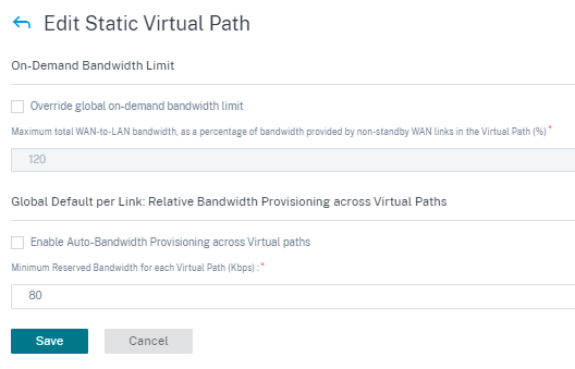
On-demand Bandwidth List:
- Override global on-demand bandwidth limit: When enabled, the global bandwidth limit values are replaced by site-specific values.
- Maximum total WAN-to-LAN bandwidth, as a percentage of bandwidth provided by non-standby WAN links in the Virtual Path (%): Update the maximum bandwidth limit, in %.
-
Global Default per Link: Relative Bandwidth Provisioning across Virtual Paths:
- Enable Auto-Bandwidth Provisioning across Virtual Paths: When enabled, the bandwidth for all the services are automatically calculated and applied according to the magnitude of bandwidth consumed by the remote sites.
- Minimum Reserved Bandwidth for each Virtual Path (Kbps): The maximum bandwidth to be reserved exclusively for each service on every WAN link.
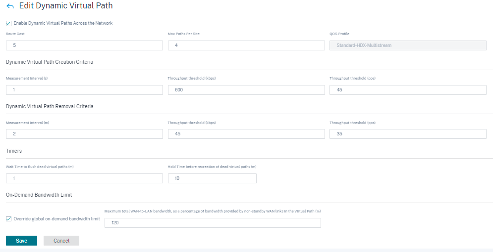
Dynamic virtual path settings
The global dynamic virtual path settings allow admins to configure dynamic virtual path defaults across the network.
A dynamic virtual path is instantiated dynamically between two sites to enable direct communication, without any intermediate SD-WAN node hops. Similarly, the dynamic virtual path connection is removed dynamically too. Both the creation and removal of dynamic virtual paths are triggered based on bandwidth thresholds and time settings.
To configure dynamic virtual paths, from the customer level, navigate to Configuration > Delivery Channels > Service Definitions, and click the Dynamic Virtual Path tile.
The following are some of the supported settings:
- Provision to enable or disable dynamic virtual paths across the network
- The route cost for dynamic virtual paths
- The QoS Profile to be used – Standard by default.
-
Dynamic Virtual Path Creation Criteria:
- Measurement interval (seconds): The amount of time over which the packet count and bandwidth are measured to determine if the dynamic virtual path must be created between two sites – in this case, between a given Branch and the Control Node.
- Throughput threshold (kbps): The threshold of total throughput between two sites, measured over the Measurement interval, at which the Dynamic Virtual Path is triggered. In this case the threshold applies to the Control Node.
- Throughput threshold (pps) - The threshold of total throughput between two sites, measured over the Measurement interval, at which the Dynamic Virtual Path is triggered.
-
Dynamic Virtual Path Removal Criteria:
- Measurement interval (minutes): The amount of time over which the packet count and bandwidth are measured to determine if a Dynamic Virtual Path must be removed between two sites – in this case, between a given Branch and the Control Node.
- Throughput threshold (kbps) - The threshold of total throughput between two sites, measured over the Measurement interval, at which the Dynamic Virtual Path is removed.
- Throughput threshold (pps) - The threshold of total throughput between two sites, measured over the Measurement interval, at which the Dynamic Virtual Path is removed.
-
Timers
- Wait time to flush dead virtual paths (m): The time after which a DEAD Dynamic Virtual Path is removed.
- Hold time before the recreation of dead virtual paths (m): The time after which a Dynamic Virtual Path removed for being DEAD can be recreated.
- On-demand Bandwidth List
- Override global on-demand bandwidth limit: When enabled, the global bandwidth limit values are replaced by site-specific values.
- Maximum total WAN-to-LAN bandwidth, as a percentage of bandwidth provided by non-standby WAN links in the Virtual Path (%): Update the maximum bandwidth limit, in %.
Click Verify Configuration to validate any audit error.