Routing
The Routing section provides the following options:
- Routing Policies
- Routing Domains
- Import Route Profiles
- Export Route Profiles
- Transit Nodes
Routing policies
Routing policies help to enable traffic steering. Based on the selection (Application routes and IP Routes) you can use different ways to steer traffic.
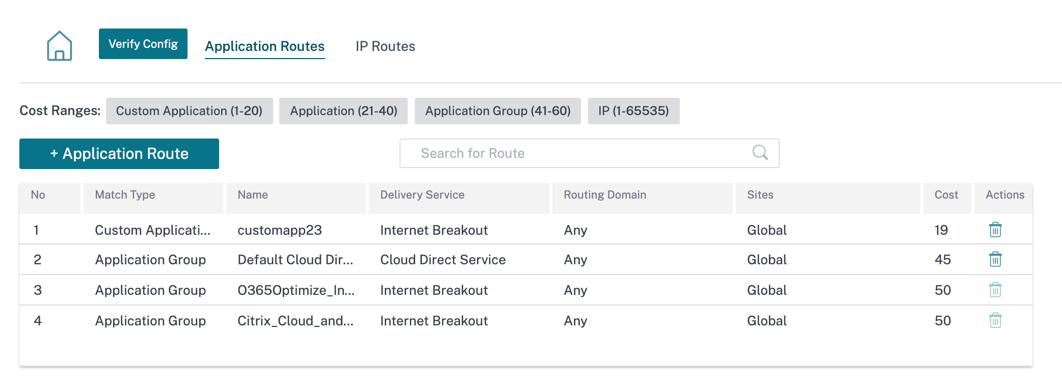
Application Routes
Click + Application Route to create application route.
-
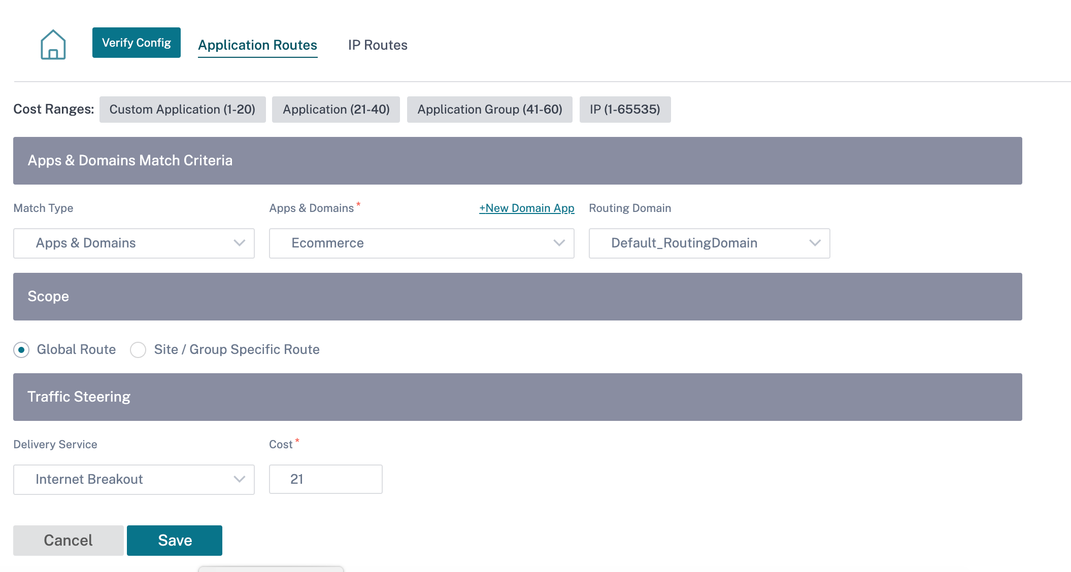
Custom Application Match Criteria:
- Match Type: Select the match type as Application/Custom Application/Application Group from the drop-down list.
- Application: Choose one application from the list.
- Routing Domain: Select a routing domain.
-
Scope: You can scope the application route at the global level or site and group specific level.
-
Traffic Steering;
- Delivery Service: Choose one delivery service from the list.
- Cost: Reflects the relative priority of each route. Lower the cost, higher the priority.
-
Eligibility Based on Path:
- Add Path: Choose a site and WAN links. If the chosen path goes down, then the application route does not receive any traffic.
If a new application route gets added, then the route cost must be in the following range:
- Custom application: 1–20
- Application: 21–40
- Application group: 41–60
Office 365 optimization
The Office 365 Optimization features adhere to the Microsoft Office 365 Network Connectivity Principles, to optimize Office 365. Office 365 is provided as a service through several service endpoints (front doors) located globally.
To achieve optimal user experience for Office 365 traffic, Microsoft recommends redirecting Office365 traffic directly to the Internet from branch environments and avoiding practices such as backhauling to a central proxy. This is because Office 365 traffic such as Outlook, Word are sensitive to latency and backhauling traffic introduces more latency resulting in poor user experience. Citrix SD-WAN allows you to configure policies to break out Office 365 traffic to the Internet. For more information, see Office 365 Optimization.
In Citrix SD-WAN Orchestrator service, by-default every network have the office 365 rule under Application Group. To navigate, go to Network Configuration > Routing > Routing Policies > Application Routes.
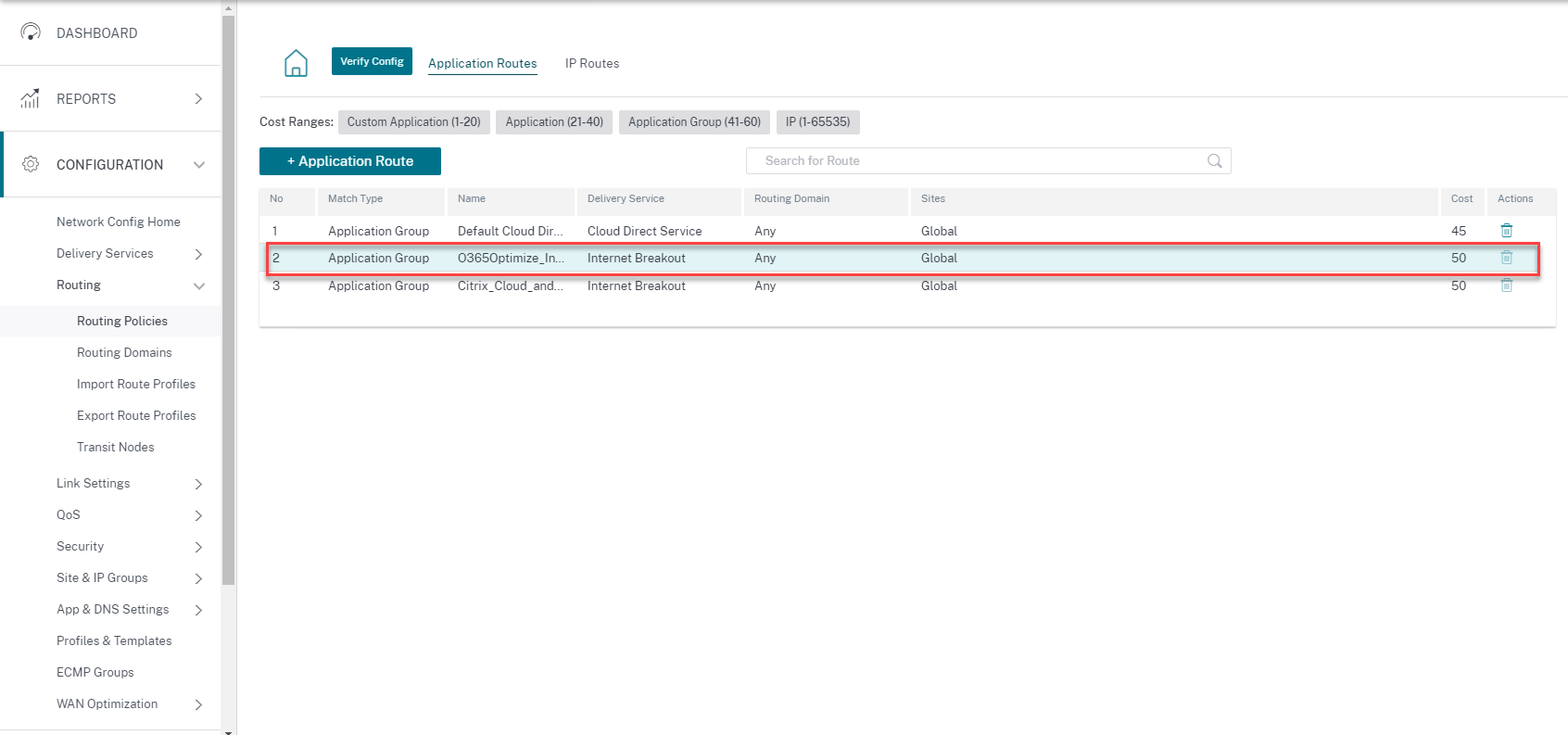
You cannot delete the rule but can configure the settings as required.
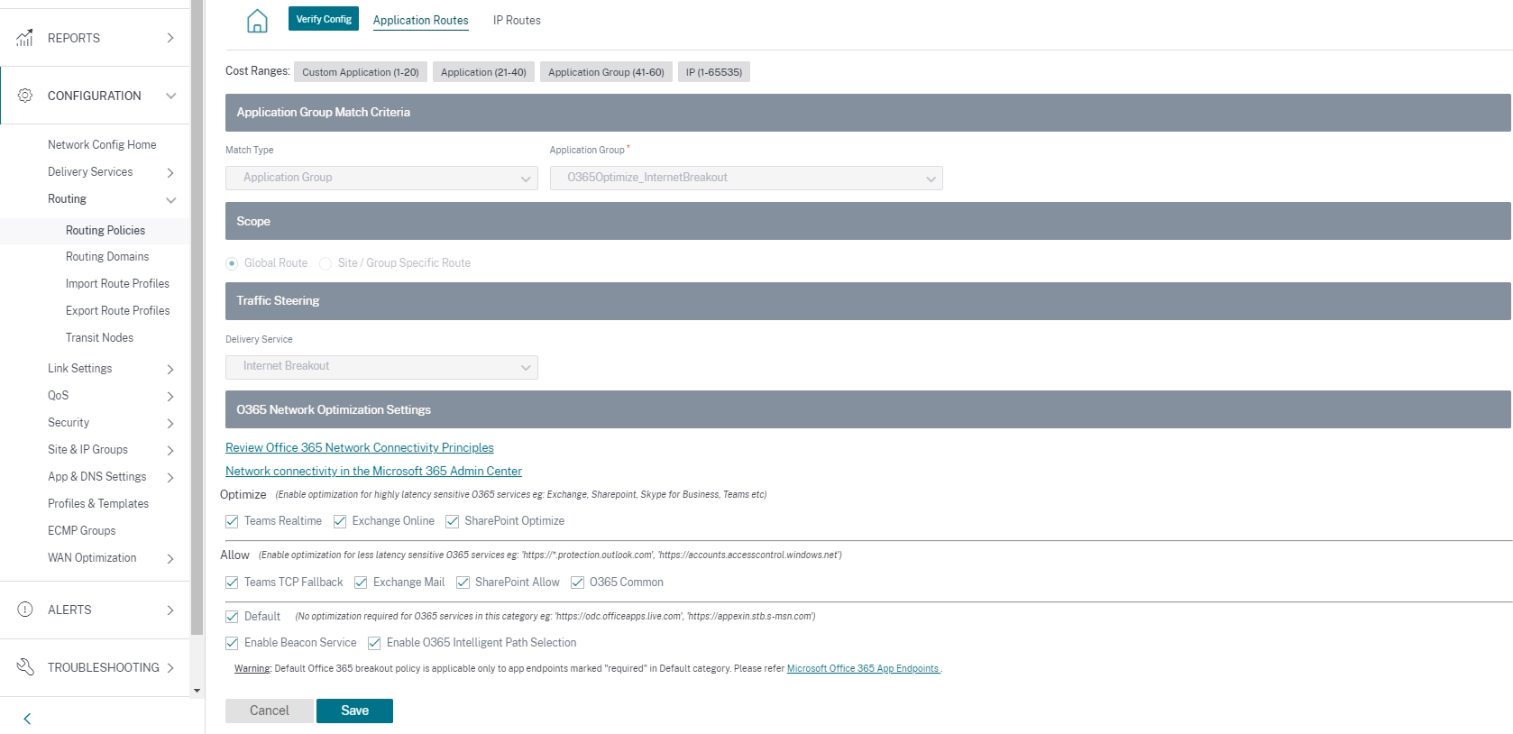
Click the office 365 rule to view the default settings Match Type, Application Group, Delivery Service, and so on. You cannot modify these default settings.
Office 365 endpoints are a set of network addresses and subnets. Endpoints are segregated into the following three categories:
-
Optimize - These endpoints provide connectivity to every Office 365 service and feature, and are sensitive to availability, performance, and latency. It represents over 75% of Office 365 bandwidth, connections, and volume of data. All the Optimize endpoints are hosted in Microsoft data centers. Service requests to these endpoints must be breakout from the branch to the Internet and must not go through the data center.
-
Allow - These endpoints provide connectivity to specific Office 365 services and features only, and are not so sensitive to network performance and latency. The representation of Office 365 bandwidth and connection count is also lower. These endpoints are hosted in Microsoft data centers. Service requests to these endpoints might be breakout from the branch to the Internet or might go through the data center.
-
Default - These endpoints provide Office 365 services that do not require any optimization, and can be treated as normal Internet traffic. Some of these endpoints might not be hosted in Microsoft data centers. The traffic in this category is not susceptible to variations in latency. Therefore, direct breaking out of this type of traffic does not cause any performance improvement when compared to Internet breakout. In addition, the traffic in this category may not always be Office 365 traffic, hence it is recommended to disable this option when enabling the Office 365 breakout in your network.
NOTE
By-default, the Optimize, Allow, and Default options are disabled. You cannot delete these settings but can enable as needed.
-
Enable Beacon Service - Citrix SD-WAN allows you to perform beacon probing and determines the latency to reach Office 365 endpoints through each WAN link. Office 365 Beacon services are enabled by default. You can disable it by clearing this option. For more information, see Office 365 Beacon service.
You can view the beacon probing availability and latency reports at Network level and Site level.
IP Routes
Go to IP Routes tab and click + IP Route to IP Route policy to steer traffic.
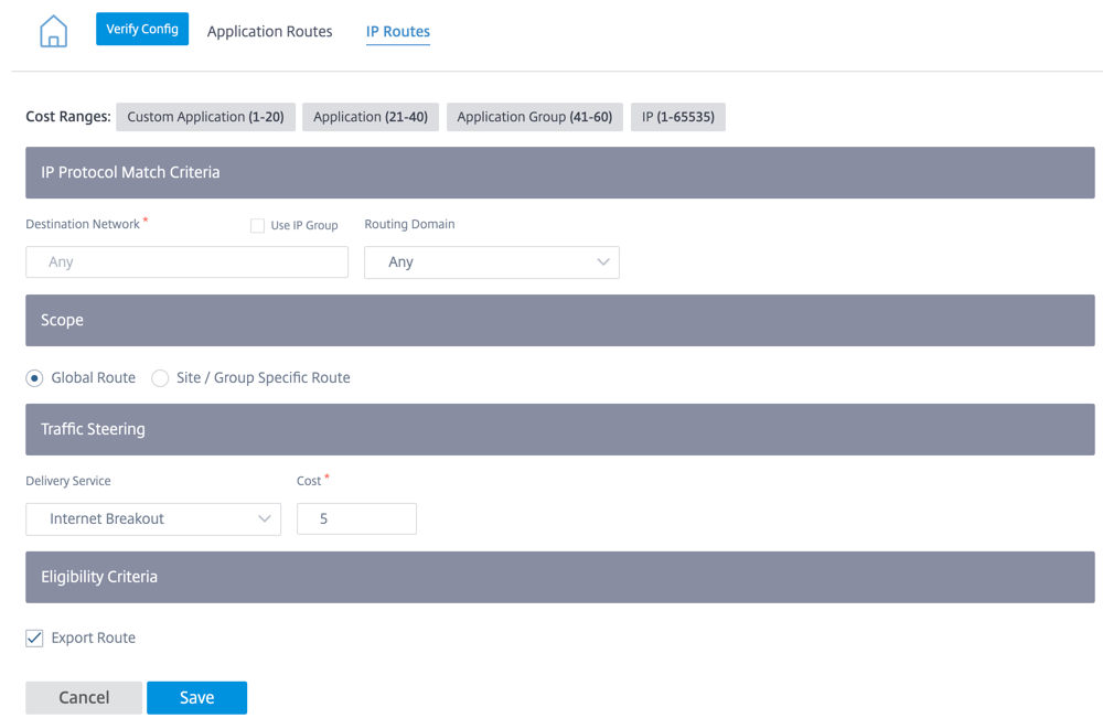
-
IP Protocol Match Criteria:
- Destination Network: Add the destination network that helps to forward the packets.
- Use IP Group: You can add a destination network or enable the Use IP Group check box to select any IP group from the drop-down list.
- Routing Domain: Select a routing domain from the drop-down list.
-
Scope: You can scope the IP route at the global level or site and group specific level.
-
Traffic Steering:
- Delivery Service: Choose one delivery service from the drop-down list.
- Cost: The cost field reflects the relative priority of each route. Lower the cost, higher the priority.
If a new IP route gets added, then the route cost must be in 1-20 range.
-
Eligibility Criteria:
- Export Route: If the Export Route check box is selected and if the route is a local route, then the route is eligible to be exported by default. If the route is an INTRANET/INTERNET based route, then for the export to work, WAN to WAN forwarding has to be enabled. If the Export Route check box is cleared, then the local route is not eligible to be exported to other SD-WAN and has local significance.
-
Eligibility based on Path:
- Add Path: Choose a site and WAN links. If the added path goes down, then the IP route does not receive any traffic.
Click Verify Config to validate any audit error.
Route Summarization
Route summarization reduces the number of routes that a router must maintain. A summary route is a single route that is used to represent multiple routes. Route summarization saves bandwidth by sending a single route advertisement, reducing the number of links between routers. Route summarization saves memory because only one route address is maintained. The CPU resources are used more efficiently by avoiding recursive lookups. You have an option to add summary routes without specifying the gateway IP address.
Routing domains
Routing domain helps to improve network security/functionality and work with the IP network routers that enables multiple routing table instances to exist in a virtual router and work simultaneously. With this functionality, the connectivity increases by enabling the network paths to be segmented without using multiple devices as the traffic is automatically segregated. VRF also increases network security and can eliminate the need for encryption and authentication.
Routing domain focuses on Layer 3 traffic through MPLS. The multiprotocol label switching or MPLS cloud in the service provider cloud environment uses multiprotocol border gateway protocol or multiprotocol BGP. Routing domain isolates traffic from source to destination through that MPLS cloud. To separate overlapping routes and make use of common services, Routing domain incorporates Route Distinguishers (RDs) and Route Targets (RTs).
The following topology describes how the routing domains work:
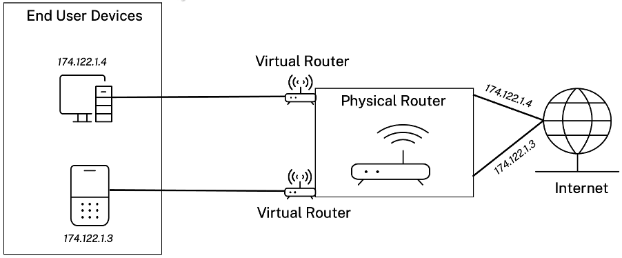
Once the routing domains are created, you can reference them at the global level (for Intranet services) or interface level.
You can also select the default routing domain that applies to all the sites.
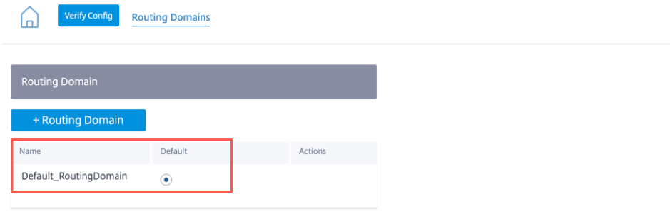
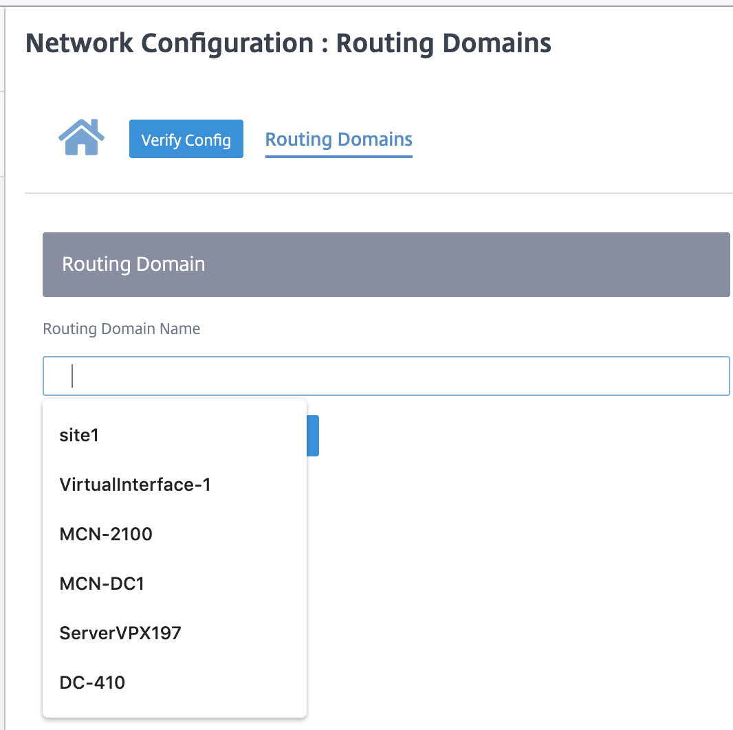
To match routes from a specific routing domain, click + Routing Domain and choose one of the configured Routing Domains from the drop-down list. Click Save.
Click Verify Config to validate any audit error.
For more information, see Routing Domain.
Inter-routing domain service
Citrix SD-WAN Orchestrator service provides Static Inter-Routing Domain Service, enabling route leaking between Routing Domains within a site or between different sites. This eliminates the need for an edge router to handle route leaking. The Inter-VRF routing service can further be used to set up routes, firewall policies, and NAT rules.
For more information see, Inter-routing domain service.
To configure the Inter-Routing Domain service through the Citrix SD-WAN Orchestrator service:
-
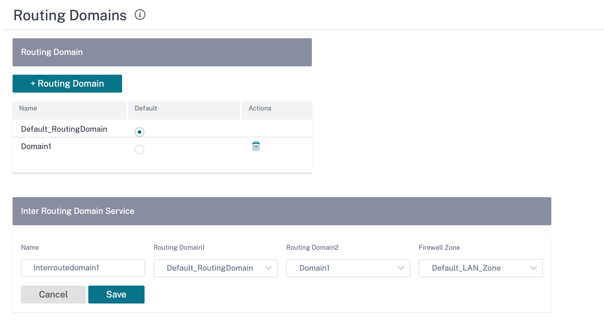
At the network level, navigate to Configuration > Routing > Routing Domains > Inter-Routing Domain Service.
-
Click + Inter-Routing Domain and enter values for the following parameters:
- Name: The name of the Inter-Routing Domain Service.
- Routing Domain 1: The first Routing Domain of the pair.
- Routing Domain 2: The second Routing Domain of the pair.
-
Firewall Zone: The Firewall Zone of the Service.
- Default: The Inter_Routing_Domain_Zone firewall zone is assigned.
- None: The service behaves like a conduit, which has no Zone and maintains the original zone of the packet.
- All Zones configured in the network might be selected.
To create routes using the Inter-routing domain service, create a route with Service type as Inter-Routing Domain Service and select the inter-routing domain service. For more information on configuring Routes, see Routing policies.
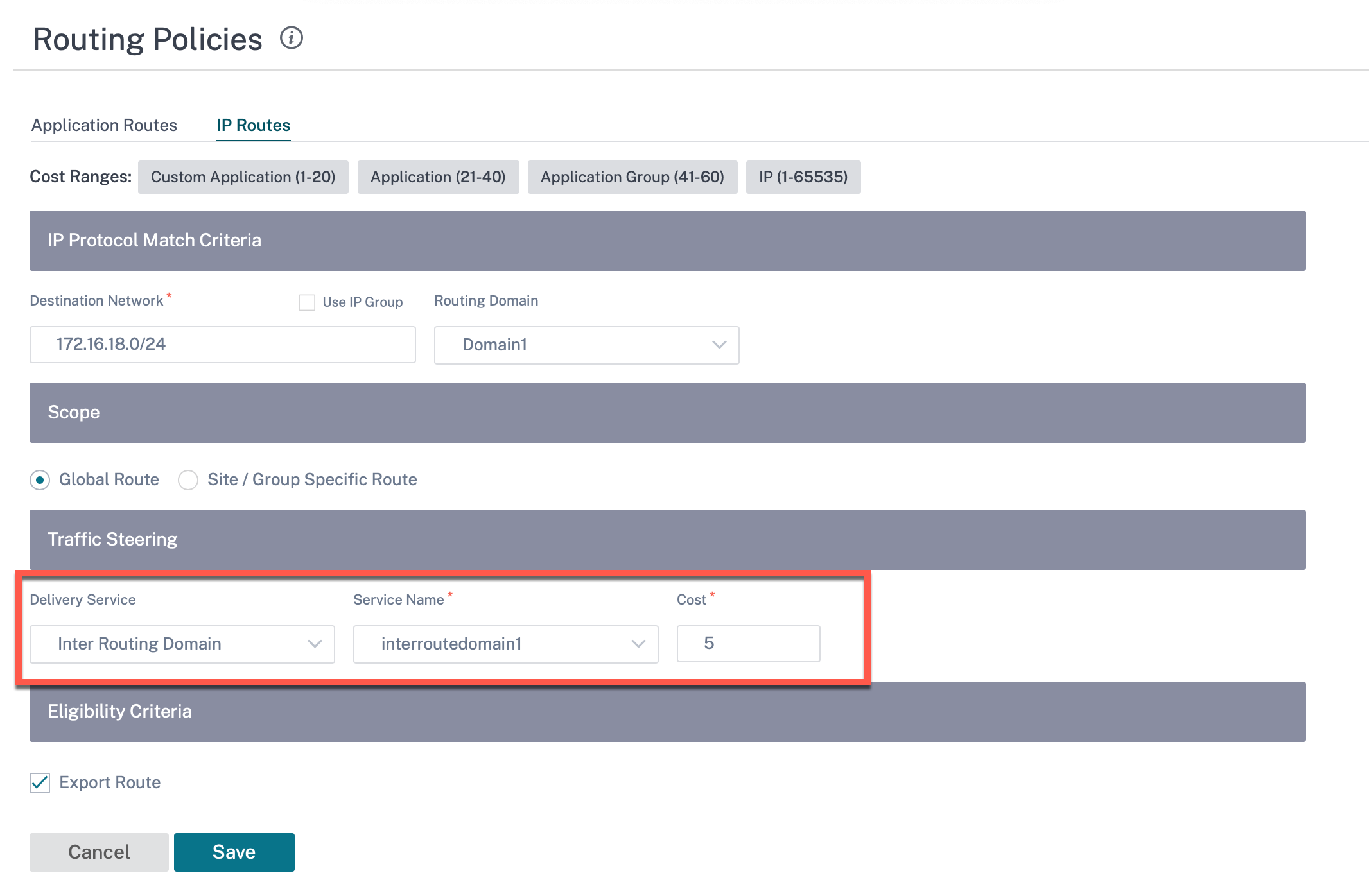
Also add a route from the other Routing Domain pair, to establish connection to and fro between the two routing domains.
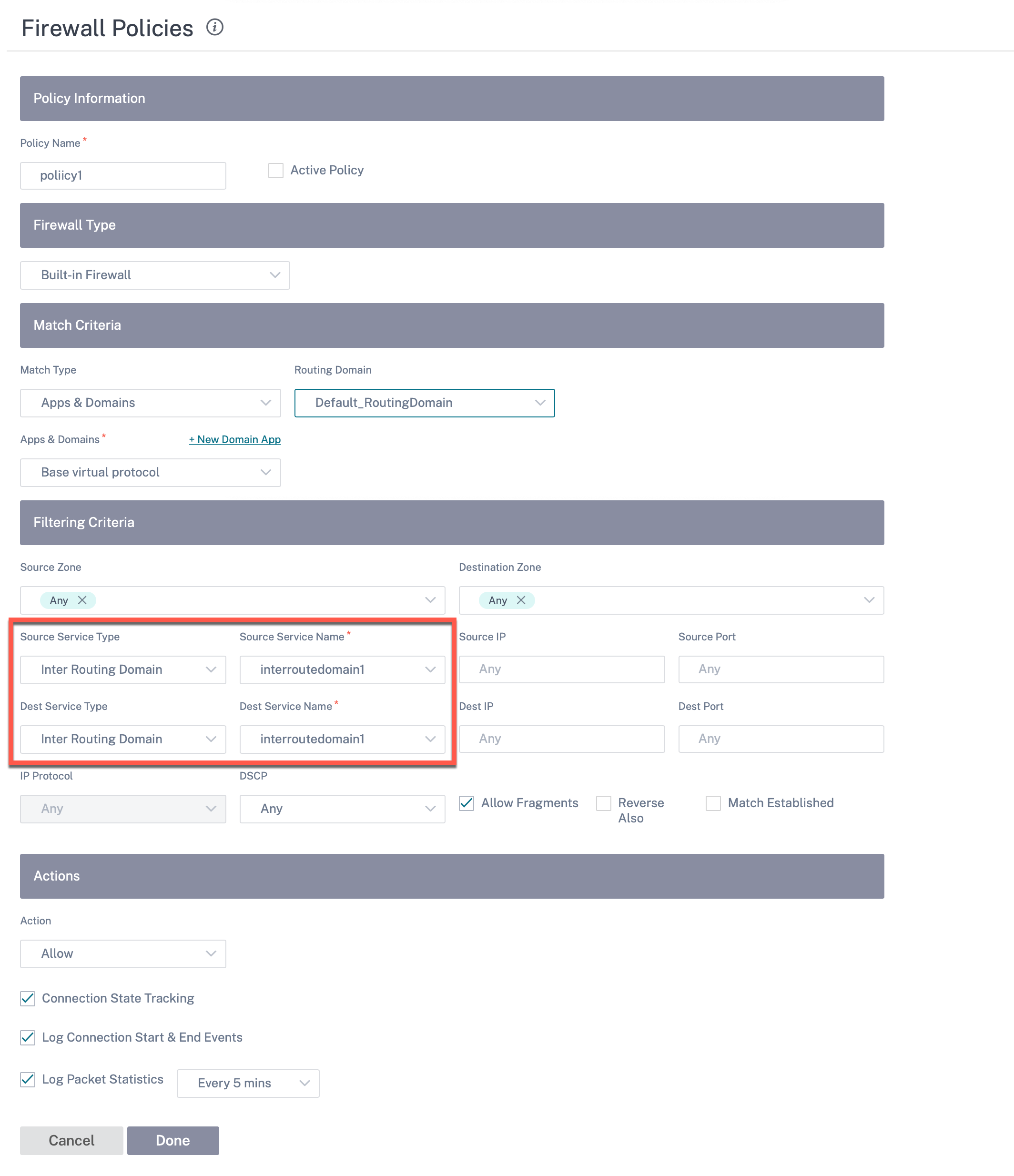
You can also configure firewall policies to control the flow of traffic between routing domains. In the firewall policies, select Inter-Routing domain service for the source and destination services and select the required firewall action. For information on configuring Firewall Policies, see Firewall policies.
You can also choose Intranet service type to configure Static and Dynamic NAT policies. For More information on configuring NAT policies, see Network Address Translation.
Import route profiles
You can configure Filters to fine-tune how route-learning takes place.
Import filter rules are rules that have to be meet before importing dynamic routes into the SD-WAN route database. By default, no routes are imported.
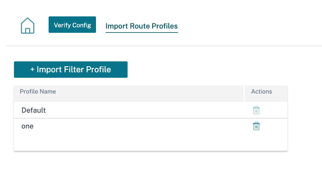
Add an Import Filter Profile with the Import Profile Name, Profile Availability, and Import Filters along with the following fields:
- Protocol - Select the protocol from the list.
- Routing Domain - To match routes from a specific routing domain, choose one of the configured Routing Domains from the list.
- Source Router - Enter the IP address and netmask of the configured network object that describes the route’s network.
- Destination IP - Enter the destination IP address.
- Prefix - To match routes by prefix, choose a match predicate from the list and enter a Route prefix in the adjacent field.
- Next Hop - Enter the next hop destination.
- Route Tag - Fill the route tag.
- Cost - The method (predicate) and the SD-WAN Route Cost that are used to narrow the selection of routes exported.
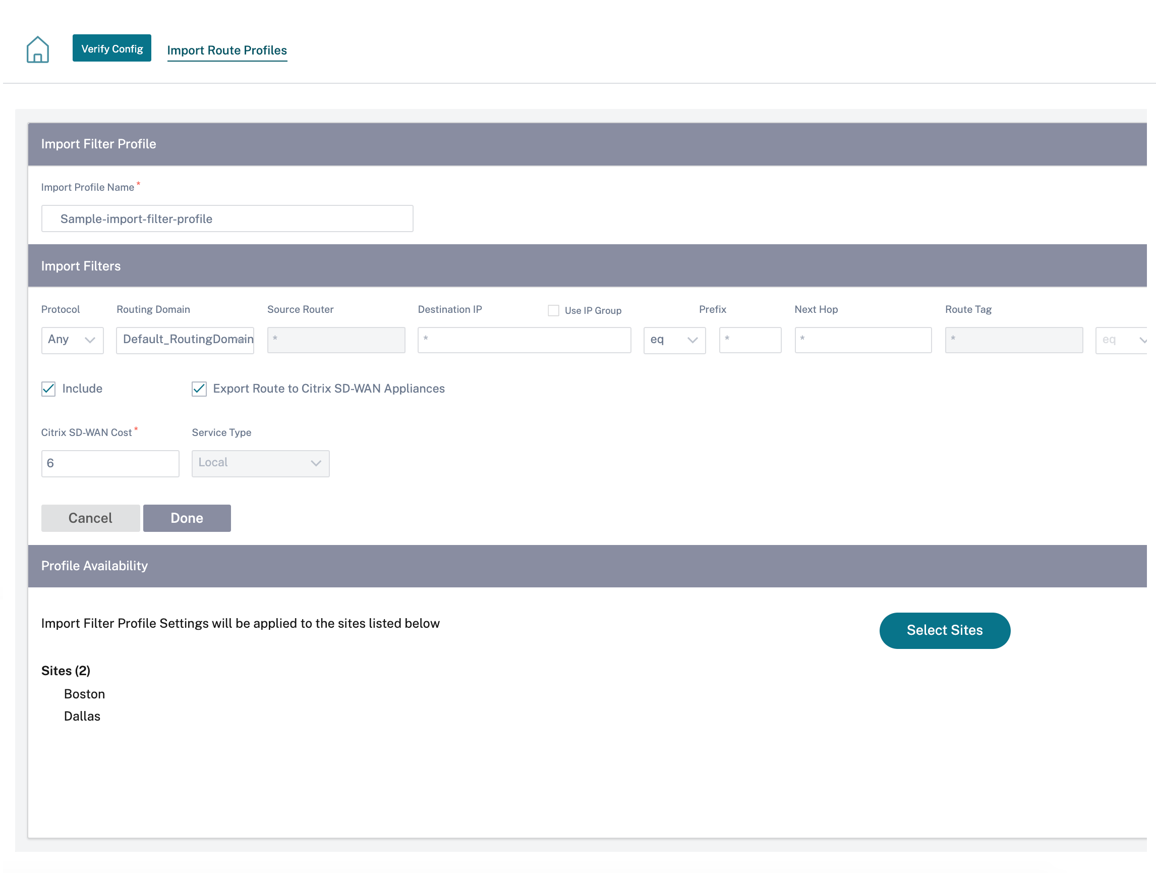
Click Verify Config to validate any audit error.
Export route profiles
Define the rules that have to meet when advertising SD-WAN routes over dynamic routing protocols. By default, all routes are advertised to peers.
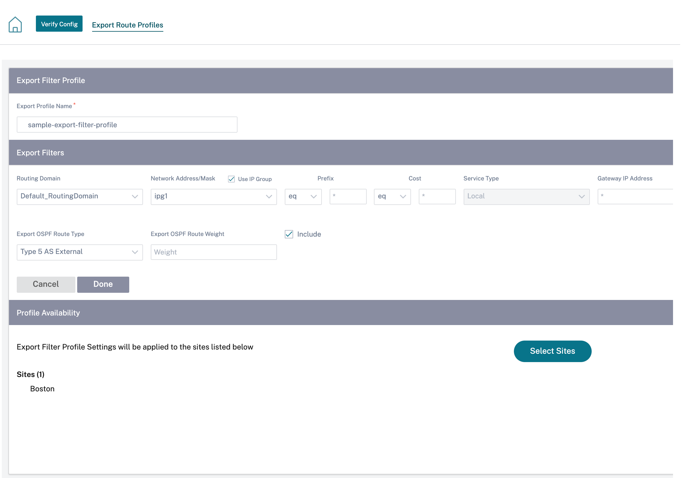
Click Verify Config to validate any audit error.
Transit nodes
Virtual overlay Transit Node
You can reduce the cost of routing by configuring a site to route data via a virtual overlay transit node. Transit nodes are used to route data to non-adjacent nodes. For example, if three nodes are connected in series A-B-C, then data from A to C can be routed via B. You can specify the transit node and the sites to be routed via the transit node in the Citrix SD-WAN Orchestrator service. The virtual paths are chosen in the ascending order of cost. Lower the cost, higher the priority.
Default global virtual overlay transit nodes
The control nodes (MCN/RCN) and the geo-control nodes (Geo-MCN/RCN) are the default global virtual overlay transit nodes in a network. Enabling hub-and-spoke communication as part of global settings allows all the sites to use the control nodes as transit nodes, by default, for site-to-site communication. If you disable hub-and-spoke communication, ensure that there are site-specific rules that enable the non-control node to act as transit nodes.
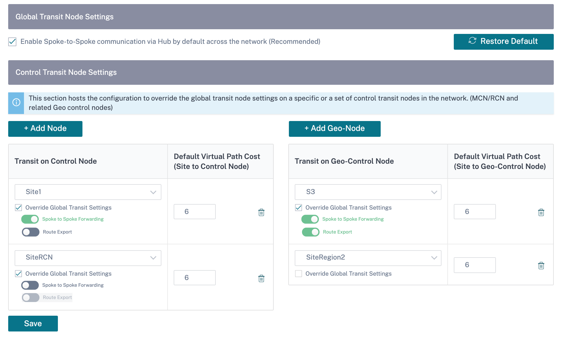
Add the control node and geo-control nodes that you want to use as virtual overlay transit nodes and specify the virtual path cost. The control nodes and geo-control nodes have 6 and 7 as the respective default virtual path costs. You can choose to change the virtual path cost as per your network requirement. Click Restore Default to restore the default virtual path costs for the default transit nodes.
Note
You can add a maximum of 3 control nodes and 3 geo-control nodes as transit nodes.
By default, WAN-to-WAN forwarding is enabled on all the paths associated with the selected control and geo-control nodes. WAN-to-WAN forwarding allows a site to act as an intermediate hop between two adjacent sites for any site-to-site, internet or intranet traffic and to act as a mediator for Dynamic Virtual Paths.
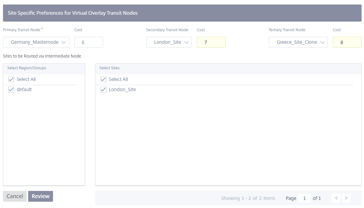
Site specific preferences for virtual overlay transit nodes
Site-specific preferences for virtual overlay transit nodes allow you to override the global virtual overlay transit node settings for all the sites in your network. You can also choose a non-control node as the primary transit node for a site. Choose a control node or geo-control node as the secondary and the tertiary transit nodes. If the primary transit node is down, the sites use the secondary transit node. If both primary and secondary transit nodes are down, the sites use the tertiary transit node. Specify the cost for the transit nodes and select the sites to which the site-specific virtual overlay transit node settings are applied.
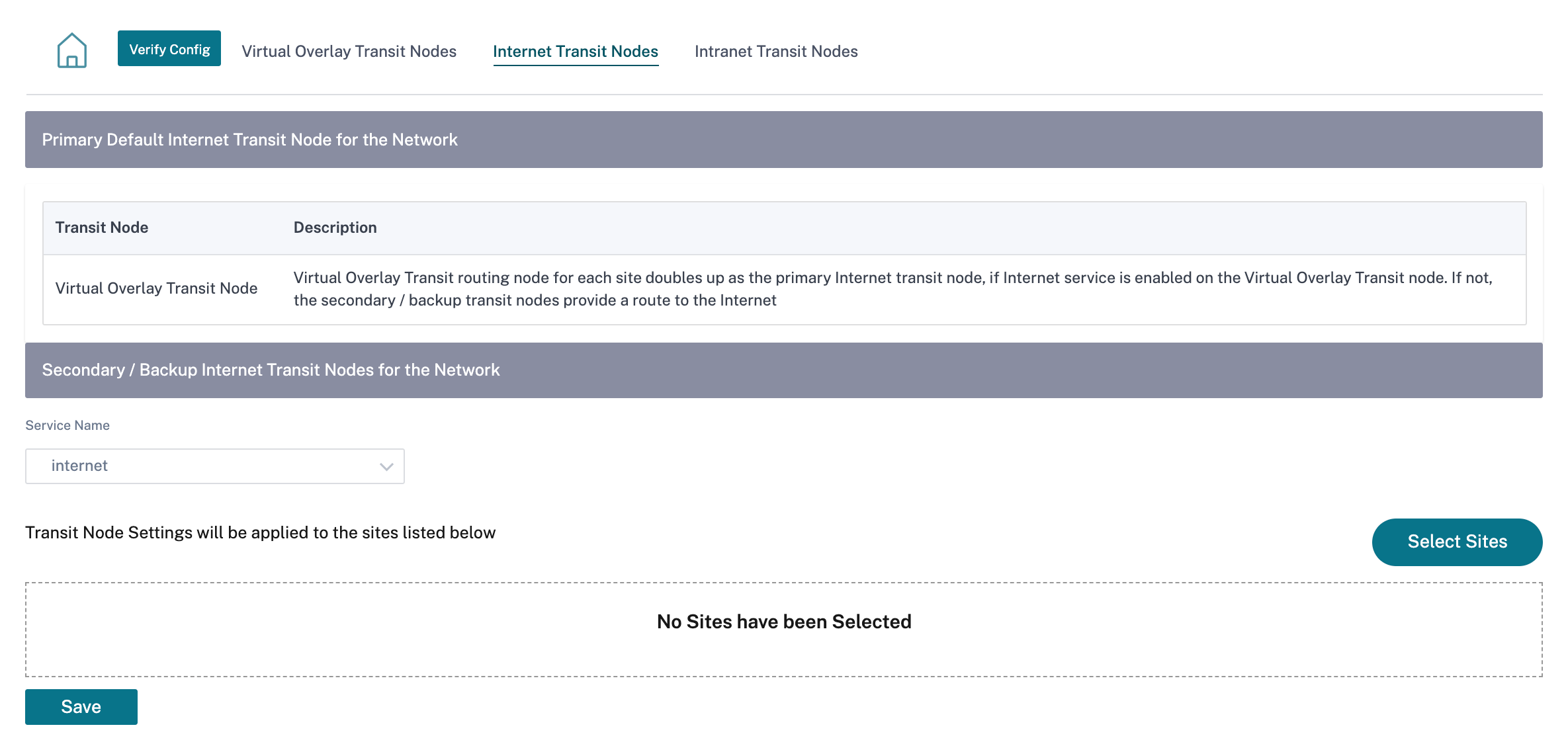
Internet Transit Node
You can add sites as Internet transit sites to enable Internet access to the sites. Sites that need direct internet connectivity, must have at least one link with Internet service enabled. That means, at least one link set to a non-zero bandwidth share %.
Each transit site can be assigned a route cost. The sites with internet service available access the internet directly since the direct route would be the lowest cost routing path. Sites without internet service can route to the internet through the configured transit sites. When the internet transit sites are configured, routes to the internet through these transit sites are automatically pushed to all the sites. Internet transit sites are the sites with Internet service enabled.
For example, if San Francisco and New York are configured as internet transit sites. Routes to the internet via San Francisco and New York automatically get pushed to all the sites.
The virtual overlay transit node with Internet service enabled acts as the primary internet transit node. If internet service is not enabled on the virtual overlay transit node the secondary / backup internet transit node provides a route to the internet.
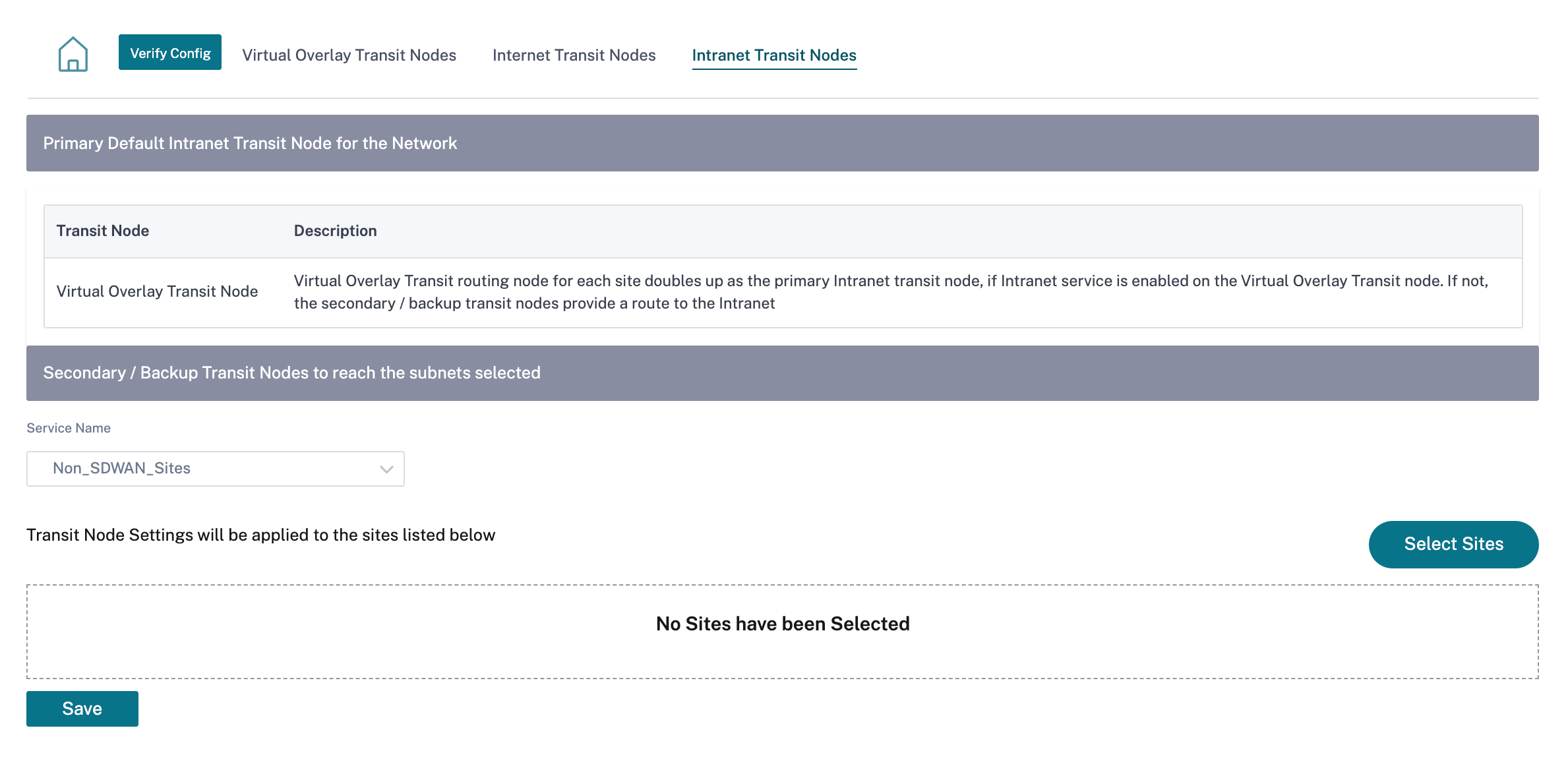
Intranet Transit Node
The intranet transit node enables all the non-intranet sites to access the configured intranet networks. Each transit site can be assigned a route cost. The available sites with intranet service, accesses the intranet networks directly since the direct route would be the lowest cost routing path. Sites without intranet service can route to the intranet networks through the configured transit sites. When the transit sites are configured, routes to intranet networks through these transit sites are automatically pushed to all the sites.
For example, if 10.2.1.0/24 is an intranet network, and Austin and Dallas are the configured transit sites. Routes to that network address through Austin and Dallas automatically get pushed to all the sites. The virtual overlay transit node with Intranet service enabled acts as the primary intranet transit node. If intranet service is not enabled on the virtual overlay transit node the secondary / backup intranet transit node provides a route to the intranet.