Virtual inline mode
In virtual inline mode, the router uses routing protocol such as PBR, OSPF, or BGP to redirect incoming and outgoing WAN traffic to the appliance, and the appliance forwards the processed packets back to the router.
Virtual inline mode is the simplest and recommended way to network SD-WAN in the data center. It allows parallel network plumbing of SD-WAN with the head-end core router while the data center is serving its existing workloads with existing infrastructure. The virtual inline mode allows us to easily define PBRs to divert LAN traffic to go through SD-WAN and get overlay benefits.
Advantages and Use-cases
The following are the advantages of Virtual Inline mode deployment:
- Seamless forwarding to SD-WAN for overlay benefits under normal conditions and seamless failover to underlying infrastructure if SD-WAN fails.
- Simple Networking and Integration requirements. The single one-arm interface from headend router to SD-WAN in virtual inline.
- Easy to deploy dynamic routing in Import only mode (export nothing) to get visibility of LAN subnets so they can be sent to remote SD-WAN peer appliances.
- Easy to define PBR on the routers (1 per WAN VIP) to indicate how to choose the physical.
Recommendations
The following are the recommendations for the Virtual Inline mode deployment:
- The virtual inline mode is best for data center networking as the SD-WAN network plumbing can be worked on parallel while the data center is serving its existing workloads with existing infrastructure.
- SD-WAN is in a one-arm interface that is managed with an SLA tracking on VIPs. If the tracking goes down, the traffic resumes routing via existing underlay infrastructure.
- Branches can also be deployed in virtual inline mode. However, they are more predominant with Inline/Gateway deployments.
Cautions
The following are the information that you need to be careful about in the Virtual Inline mode:
- Proper care must be taken to distinctly MAP the SD-WAN logical VIP of a WAN link defined to the right physical interface (else this might cause undesirable issues in WAN metric assessment and choice of WAN paths).
- Proper design considerations are to be made to know if all traffic is diverted via SD-WAN or only specific traffic.
- This means SD-WAN must be dedicated some share of bandwidth exclusively for itself that must be set on the interfaces such that SD-WAN’s capacity is not used by other non-SD-WAN traffic causing undesirable outcomes.
- Bandwidth accounting issues and congestion issues might occur if SD-WAN WAN links capacity is defined incorrectly.
- Dynamic routing can cause some issues if improperly designed where if the SD-WAN routes data center and branch VIPs are exported to the headend and if routing is influenced towards SD-WAN, overlay packets start looping and cause undesirable outcomes.
- Dynamic routing must be properly administered considering all potential factors of what to learn/what to advertise.
- One-arm physical interface might become a bottleneck sometimes. Needs some design considerations in those lines as it caters to both upload/download and also acts as LAN to LAN and LAN to WAN/WAN to LAN traffic from SD-WAN.
- Excessive LAN to LAN traffic might be a point to note during design.
- If the dynamic routing is not used, there must be proper care if administering all LAN subnets, which if not, might cause undesirable routing issues.
- There are potential routing loop issues if you define some default route (0.0.0.0/0) on the SD-WAN in the virtual inline to point back to the headend router. In such situations, if the virtual path went down, any traffic coming from the data center LAN (like monitoring traffic) is looped back to the headend and back to SD-WAN causing undesirable routing issues (If the virtual path is down, the remote branch subnets become reachable NO causing the default route to be HIT, that causes the loop issues).
Before you begin
Before you begin the configuration, ensure that you have a good understanding of the network topology and gathered the details of the site.
The following is an example of an SD-WAN network where the data center is configured in virtual inline mode.
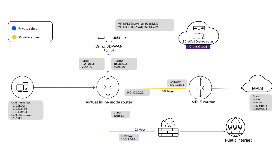
The details of the site are provided in the following table:
| Site details | Virtual inline mode |
|---|---|
| Site Name | San Jose Data Center |
| Management IP | 172.30.2.10/24 |
| Security Key | If any |
| Model/Edition | 4100 |
| Mode | Virtual Inline Mode |
| Topology | 2 x WAN Path |
| VIP Address | 192.168.1.10/24 - MPLS, 192.168.2.10/24 - Internet, Public IP - w.x.y.z |
| Gateway MPLS | 10.20.0.1 |
| Gateway Internet | 10.19.0.1 |
| Link Speed | MPLS - 100 Mbps, Internet - 20 Mbps |
| Route | Add a route on the SD-WAN SE Appliance on how to reach the LAN Subnets through any of the physical interfaces. |
| VLANs | MPLS - VLAN 10, Internet - VLAN 20 |
Configure virtual inline mode
-
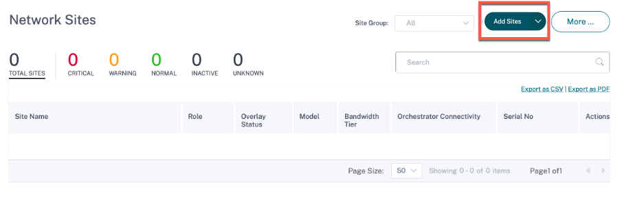
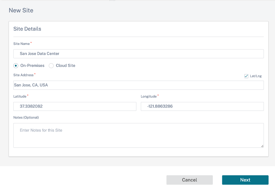
At the customer level configuration, navigate to Configuration > Network Home. Click Add Sites. Enter the site name, select On-Premises check box, and add other details as required.
-
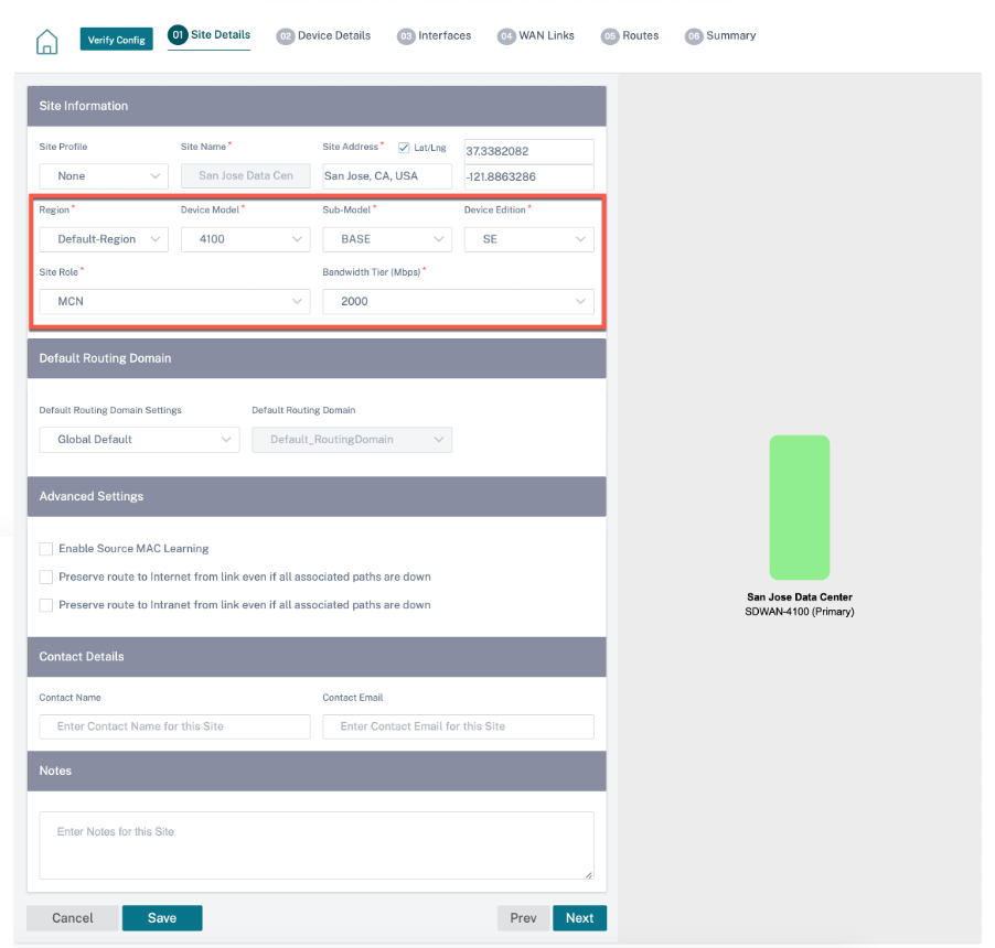
Click Next and navigate to Site Details tab. Select the site role as MCN. select the device model, edition, and bandwidth as per your preference.
-
Click Next and navigate to Device Details tab. Enter the serial number of the appliance.
-
Click Next and navigate to the Interfaces tab. Click + Interface.
-
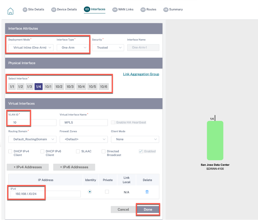
Select Virtual Inline (One-Arm) from the Deployment Mode drop-down list and One-Arm as the Interface Type. Select the Ethernet interface that connects to the Virtual Inline mode router. As per this topology, add two virtual LANs with the same physical interface; one for MPLS and one for Internet.
To add the first VLAN, in the Virtual Interfaces section, enter the VLAN ID, name for the virtual interface, and IP address. Click Done.
-
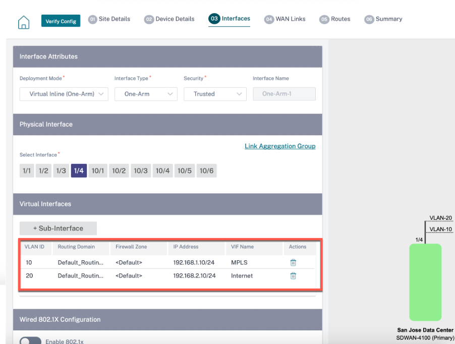
Click + Sub-Interface to add another VLAN and then enter the virtual interface details. Click Done at the bottom of the screen to navigate to the next tab.
-
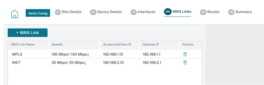
Click Next and navigate to WAN Links tab. Click + WAN Link and select the Create New radio button. Add two WAN links; One for MPLS and one for Internet.
To add an internet WAN link, select Public Internet as the Access Type. Provide an ISP name for the WAN link, select the speed. Select Internet from the Virtual Interface drop-down list. Enter the IP address of the access interface and the gateway. Click Done.
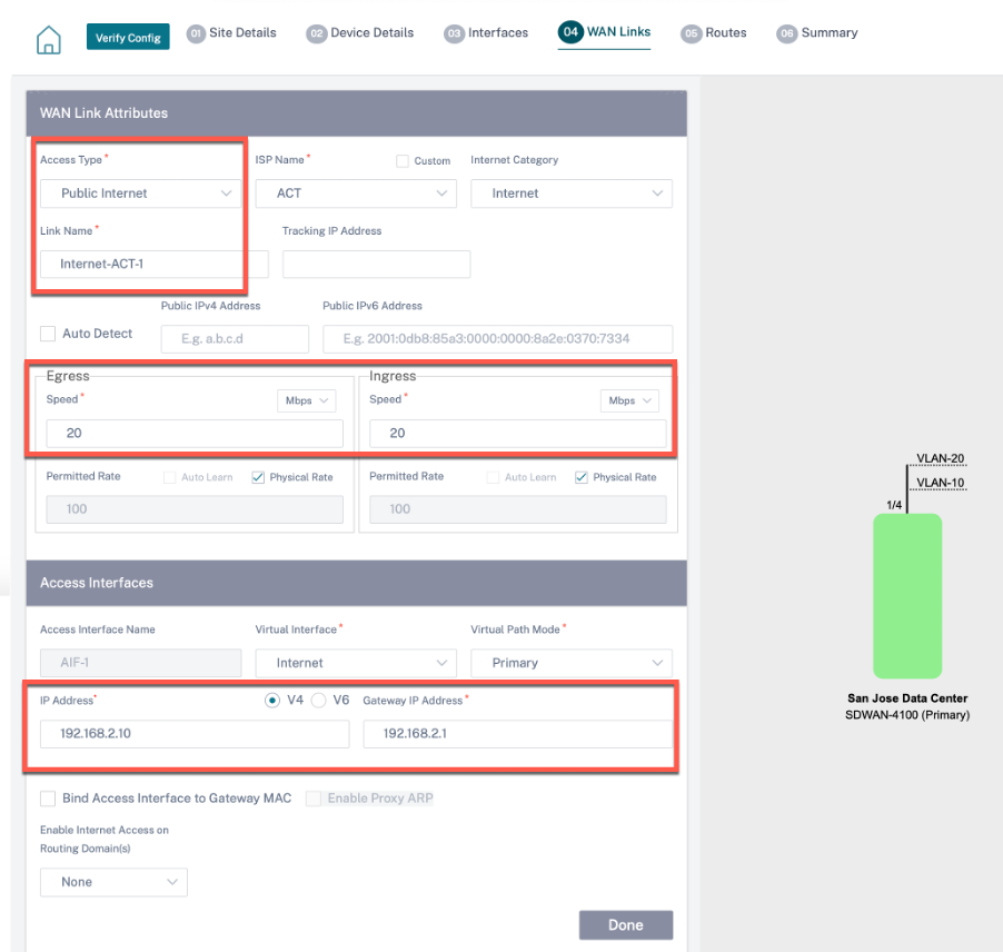
To add an MPLS WAN link, from the WAN links* tab, click + WAN Link and select the Create New radio button. Select MPLS as the Access Type. Select the ISP Name and the name of the WAN link gets populated automatically. Select speed and choose the MPLS from the Virtual Interface drop-down list. Enter the IP address of the access interface and the gateway. Click Done.
-
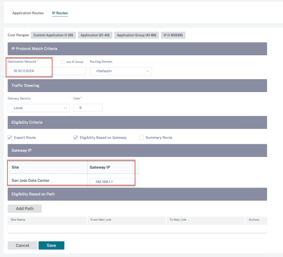
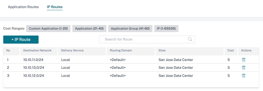
Click Next and navigate to Routes > IP Routes tab. Add a route on the SD-WAN appliance on how to reach the LAN Subnets (10.10.11.0/24, 10.10.12.0/24, 10.10.13.0/24, and so on) through any of the physical interfaces. Click Save. Repeat this step to add more routes.
-
Click Save and then Verify to validate the configurations. If any errors observed, fix them before proceeding further.