Configure cloud connector tunnel between a datacenter and AWS/Azure
You can configure a cloud connector tunnel between a datacenter and AWS, or Azure cloud.
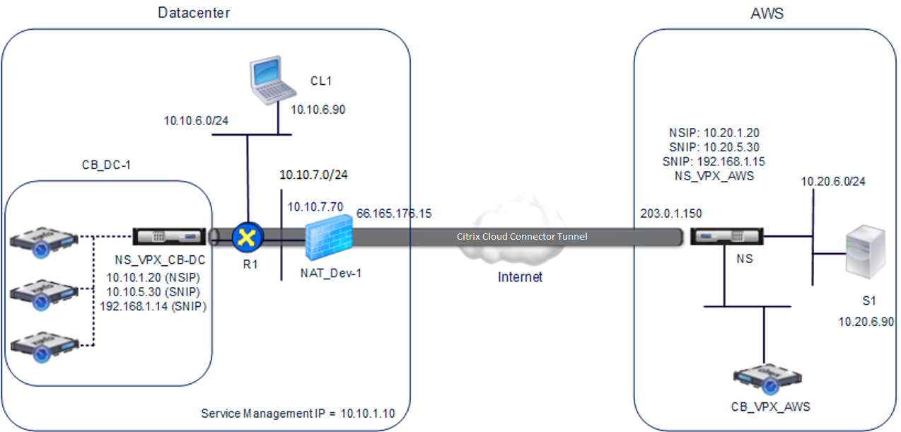
Consider an example in which a Citrix Cloud Connector tunnel is configured between Citrix SD-WAN WANOP appliance CB_DC-1, which is deployed in WCCP/PBR one-arm mode in a datacenter, and AWS cloud. CB_DC-1 is connected to router R1. A NAT device is also connected to R1 for connections between the datacenter and Internet.
Note: The settings in the example would also work for any type of Citrix SD-WAN WANOP deployment. This setting in this example includes policy based routes instead of netbridge for allowing the desired subnet’s traffic to pass through the Citrix Cloud Connector tunnel.
As shown in the following figure, the Citrix Cloud connector tunnel is established between Citrix virtual appliance NS_VPX_CB-DC, running on the Citrix SD-WAN WANOP appliance CB_DC-1, and Citrix virtual appliance NS_VPX-AWS running on AWS cloud. For WAN optimizing the traffic flow over the Citrix Cloud Connector tunnel, NS_VPX_CB-DC is paired to Citrix SD-WAN WANOP instances running on CB_DC-1, and on the AWS side, Citrix SD-WAN WANOP virtual appliance CB_VPX-AWS running on AWS is paired to NS_VPX-AWS.
The following table lists the settings in the datacenter in this example.
| Entity | Name | Details |
|---|---|---|
| IP address of client CL1 | 10.10.6.90 | |
| Settings on NAT device NAT-Dev-1 | ||
| NAT IP address on public side | 66.165.176.15 * | |
| NAT IP address on private side | 10.10.7.70 | |
| Settings on CB_DC-1 | ||
| Management service IP address of CB_DC-1 | 10.10.1.10 | |
| Settings on NS_VPX_CB-DC running on CB_DC-1 | ||
| The NSIP address | 10.10.1.20 | |
| SNIP address | 10.10.5.30 | |
| IPSec profile | CBC_DC_AWS_IPSec_Profile | IKE version = v2, Encryption algorithm = AES, Hash algorithm = HMAC SHA1 |
| Cloud Connector tunnel | CBC_DC_AWS | Local endpoint IP address of the Cloud Connector tunnel = 10.10.5.30, Remote endpoint IP address of the Cloud Connector = Public EIP address mapped to Cloud Connector endpoint address (SNIP) on NS_VPX-AWS on AWS = 203.0.1.150*, Tunnel protocol = GRE and IPSEC, IPSec profile name = CBC_DC_AWS_IPSec_Profile |
| Policy based route | CBC_DC_AWS_PBR | Source IP range = Subnet in the datacenter = 10.10.6.0-10.10.6.255, Destination IP range =Subnet in AWS =10.20.6.0-10.20.6.255, Next hop type = IP Tunnel, IP tunnel name = CBC_DC_AWS |
*These should be public IP addresses.
The following table lists the settings on AWS cloud in this example.
| Entity | Name | Details |
|---|---|---|
| IP address of server S1 | 10.20.6.90 | |
| Settings on NS_VPX-AWS | ||
| NSIP address | 10.20.1.20 | |
| Public EIP address mapped to the NSIP address | 203.0.1.120* | |
| SNIP address | 10.20.5.30 | |
| Public EIP address mapped to the SNIP address | 203.0.1.150* | |
| IPSec profile | CBC_DC_AWS_IPSec_Profile | |
| IKE version = v2, Encryption algorithm = AES, Hash algorithm = HMAC SHA1 | ||
| Cloud Connector tunnel | CBC_DC_AWS | Local endpoint IP address of the Cloud Connector tunnel =10.20.5.30, Remote endpoint IP address of the Cloud Connector tunnel = Public NAT IP address of NAT device NAT-Dev-1 in the datacenter = 66.165.176.15*, Tunnel protocol = GRE and IPSEC, IPSec profile name = CBC_DC_AWS_IPSec_Profile |
| Policy based route | CBC_DC_AWS_PBR | Source IP range = Subnet in the AWS = 10.20.6.0-10.20.6.255, Destination IP range = Subnet in datacenter = 10.10.6.0-10.10.6.255, Next hop type = IP Tunnel, IP tunnel name = CBC_DC_AWS |
*These should be public IP addresses.
Both NS_VPX_CB-DC, on CB_DC-1, and NS_VPX-AWS function in L3 mode. They enable communication between private networks in the datacenter and AWS cloud. NS_VPX_CB-DC and NS_VPX-AWS enable communication between client CL1 in the datacenter and server S1 in the AWS cloud through the Cloud Connector tunnel. Client CL1 and server S1 are on different private networks.
Note: AWS does not support L2 mode. Therefore, it is necessary to have only L3 mode enabled on both the endpoints.
For proper communication between CL1 and S1, L3 mode is enabled on NS_VPX_CB-DC and NS_VPX-AWS, and routes are configured as follows:
-
R1 has a route for reaching S1 through NS_VPX_CB-DC.
-
NS_VPX_CB-DC has a route for reaching NS_VPX-AWS through R1.
-
S1 should have a route reaching CL1 through NS_VPX-AWS.
-
NS_VPX-AWS has a route for reaching NS_VPX_CB-DC through an upstream router.
The following are the routes configured on various network devices in the datacenter for the Cloud Connector tunnel to work properly:
| Routes | Network | Gateway |
|---|---|---|
| Routes on router R1 | ||
| Route for reaching server S1 | 10.20.6.X/24 | Tunnel endpoint SNIP address of NS_VPX_CB-DC = 10.10.5.30 |
| Route for reaching remote end point of the Cloud Connector tunnel | EIP address mapped to the Cloud connector SNIP address of NS_VPX-AWS = 203.0.1.50 | Private IP address of the NAT device = 10.10.7.70 |
| Routes on NS_VPX_CB-DC | ||
| Route for reaching NS_VPX-AWS | EIP address mapped to the Cloud connector SNIP address of NS_VPX-AWS = 203.0.1.50 | IP address of R1 = 10.10.5.1 |
The following are the routes configured on various network devices on AWS cloud for the Cloud Connector tunnel to work properly:
| Routes | Network | Gateway |
|---|---|---|
| Routes on server S1 | ||
| Route for reaching client CL1 | 10.10.6.X/24 | Tunnel endpoint SNIP address of NS_VPX-AWS = 10.10.6.1 |
| Routes on Citrix virtual appliance NS_VPX-AWS | ||
| Route for reaching NS_VPX_CB-DC | Public IP address of NAT_Dev-1 in the datacenter = 66.165.176.15* | IP address of the upstream router on AWS |
Following is the traffic flow of a request packet from Client CL1 in the Cloud Connector tunnel:
-
Client CL1 sends a request to server S1.
-
The request reaches the Citrix virtual appliance NS_VPX_CB-DC running on Citrix SD-WAN WANOP appliance CB_DC-1.
-
NS_VPX_CB-DC forwards the packet to one of the Citrix SD-WAN WANOP instances running on the Citrix SD-WAN WANOP appliance CB_DC-1 for WAN optimization. After processing the packet, the Citrix SD-WAN WANOP instance returns the packet to NS_VPX_CB-DC.
-
The request packet matches the condition specified in PBR entity CBC_DC_AWS_PBR (configured in NS_VPX_CB-DC), because the source IP address and the destination IP address of the request packet belong to the source IP range and destination IP range, respectively, set in CBC_DC_AWS_PBR.
-
Because the Cloud connector tunnel CBC_DC_AWS is bound to CBC_DC_AWS_PBR, the appliance prepares the packet to be sent across the CBC_DC_AWS tunnel.
-
NS_VPX_CB-DC uses the GRE protocol to encapsulate each of the request packets by adding a GRE header and a GRE IP header to the packet. The GRE IP header has the destination IP address set to the IP address of the Cloud connector tunnel (CBC_DC-AWS) end point on AWS side.
-
For Cloud Connector tunnel CBC_DC-AWS, NS_VPX_CB-DC checks the stored IPSec security association (SA) parameters for processing outbound packets, as agreed between NS_VPX_CB-DC and NS_VPX-AWS. The IPSec Encapsulating Security Payload (ESP) protocol in NS_VPX_CB-DC uses these SA parameters for outbound packets, to encrypt the payload of the GRE encapsulated packet.
-
The ESP protocol ensures the packet’s integrity and confidentiality by using the HMAC hash function and the encryption algorithm specified for the Cloud Connector tunnel CBC_DC-AWS. The ESP protocol, after encrypting the GRE payload and calculating the HMAC, generates an ESP header and an ESP trailer and inserts them before and at the end of the encrypted GRE payload, respectively.
-
NS_VPX_CB-DC sends the resulting packet to NS_VPX-AWS.
-
NS_VPX-AWS checks the stored IPSec security association (SA) parameters for processing inbound packets, as agreed between CB_DC-1 and NS_VPX-AWS for the Cloud Connector tunnel CBC_DC-AWS. The IPSec ESP protocol on NS_VPX-AWS uses these SA parameters for inbound packets, and the ESP header of the request packet, to decrypt the packet.
-
NS_VPX-AWS then decapsulates the packet by removing the GRE header.
-
NS_VPX-AWS forwards the resulting packet to CB_VPX-AWS, which applies WAN optimization related processing to the packet. CB_VPX-AWS then returns the resulting packet to NS_VPX-AWS.
-
The resulting packet is the same packet as the one received by CB_DC-1 in step 2. This packet has the destination IP address set to the IP address of server S1. NS_VPX-AWS forwards this packet to server S1.
-
S1 processes the request packet and sends out a response packet. The destination IP address in the response packet is the IP address of client CL1, and the source IP address is the IP address of server S1.