This content has been machine translated dynamically.
Dieser Inhalt ist eine maschinelle Übersetzung, die dynamisch erstellt wurde. (Haftungsausschluss)
Cet article a été traduit automatiquement de manière dynamique. (Clause de non responsabilité)
Este artículo lo ha traducido una máquina de forma dinámica. (Aviso legal)
此内容已经过机器动态翻译。 放弃
このコンテンツは動的に機械翻訳されています。免責事項
이 콘텐츠는 동적으로 기계 번역되었습니다. 책임 부인
Este texto foi traduzido automaticamente. (Aviso legal)
Questo contenuto è stato tradotto dinamicamente con traduzione automatica.(Esclusione di responsabilità))
This article has been machine translated.
Dieser Artikel wurde maschinell übersetzt. (Haftungsausschluss)
Ce article a été traduit automatiquement. (Clause de non responsabilité)
Este artículo ha sido traducido automáticamente. (Aviso legal)
この記事は機械翻訳されています.免責事項
이 기사는 기계 번역되었습니다.책임 부인
Este artigo foi traduzido automaticamente.(Aviso legal)
这篇文章已经过机器翻译.放弃
Questo articolo è stato tradotto automaticamente.(Esclusione di responsabilità))
Translation failed!
Deployment Worksheet
Note
Use this worksheet only when provisioning a factory-reset appliance with the release 9.3 configuration wizard. If you are simply upgrading a previously configured system to release 9.3, your appliance retains its previous configuration, which will be different.
The appliance uses at least two ports: the management port (typically 0/1) and the traffic port (such as 10/1). Inline mode uses traffic ports in pairs, such as ports 10/1 and 10/2. Ports must be selected in advance, because the configuration depends on their identity.
The appliance uses three subnets directly: the management subnet, the external traffic subnet, and the internal traffic subnet. Multiple IP addresses are used on each subnet. Each subnet must be specified along with the correct subnet mask.
The following figure is a worksheet for these parameters. It supports inline and WCCP modes, with and without high availability. The table below the figure describes what each entry means.
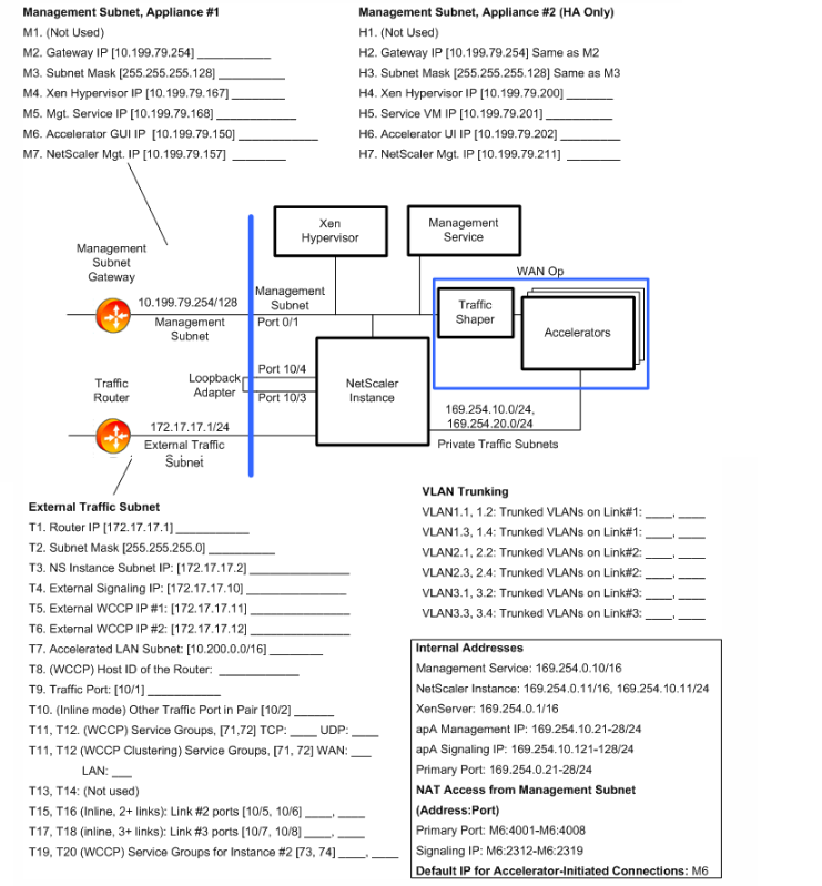
Table 1.Deployment worksheet parameters
| Parameter | Example | Your Value | Description | |
|---|---|---|---|---|
| Management Subnet | ||||
| M2. | Gateway IP address | 10.199.79.254 | Default gateway serving the management subnet. | |
| M3. | Subnet Mask | 255.255.255.128 | Subnet mask for the management subnet. | |
| M4. | Xen Hypervisor IP address | 10.199.79.225 | IP address of Xen Hypervisor. | |
| M5. | Service VM IP address | 10.199.79.226 | IP address of Management Service VM, which controls configuration. | |
| M6. | Accelerator UI | 10.199.79.227 | Accelerator GUI, also called the Broker UI, which manages the instances as a unit. | |
| M7. | NetScaler Management IP address | 10.199.79.245 | IP address of the NetScaler instance’s GUI and CLI interfaces. | |
| External Traffic Subnet | ||||
| T1. | Router IP address | 172.17.17.1 | IP address of router on external traffic subnet. | |
| T2. | Subnet Mask | 255.255.255.0 | Subnet mask of external traffic subnet. | |
| T3. | NetScaler IP address | 172.17.17.2 | NetScaler IP address on external traffic subnet. | |
| T4. | External Signaling IP address | 172.17.17.10 | Traffic to this IP address is load-balanced between the signaling IP addresses of the accelerators. | |
| T5. | External WCCP IP address #1 | 172.17.17.11 | Maps through NAT to WCCP VIP on accelerator #1. | |
| T6. | External WCCP IP address #2 | 172.17.17.12 | Maps through NAT to WCCP VIP on accelerator #2. | |
| T7. | Local LAN Subnets | 10.200.0.0/16 | The local LAN subnet to be accelerated. This is the only subnet that receives acceleration. | |
| T8. | GRE Router Host ID | NA | WCCP-GRE only. Host ID of GRE router. | |
| T9. | Traffic Port | 10/1 | Port used for accelerated traffic. | |
| T10+. | (Inline) more Traffic Port | Other traffic port in pair. | ||
| T11, T12 | (WCCP) Service Groups: TCP, UDP | 71, 72 | Service groups used by accelerator #1 for WCCP. First is for TCP traffic, second is for UDP. | |
| T13, T14 | (Not used) | |||
| T15, T16 | (Inline) Ports used by link #2 | 10/5, 10/6 | If multiple links are used with inline mode, these ports are used for link #2. | |
| T17, T18 | (Inline) Ports used by link #3 | 10/7, 10/8 | If multiple links are used with inline mode, these ports are used for link #3. | |
| VLAN1.1, VLAN1.2, VLAN1.3, VLAN1.4 | External VLANs for Bridge #1 | 412 | When VLAN trunking is used, these are tagged VLANs crossing bridge #1. | |
| VLAN2.1, VLAN2.2, VLAN2.3, VLAN2.4 | When VLAN trunking is used, these are tagged VLANs crossing bridge #2. | |||
| VLAN3.1, VLAN3.2, VLAN3.3, VLAN3.4 | External VLANs for Bridge #1 | When VLAN trunking is used, these are tagged VLANs crossing bridge #3. |
Share
Share
In this article
This Preview product documentation is Cloud Software Group Confidential.
You agree to hold this documentation confidential pursuant to the terms of your Cloud Software Group Beta/Tech Preview Agreement.
The development, release and timing of any features or functionality described in the Preview documentation remains at our sole discretion and are subject to change without notice or consultation.
The documentation is for informational purposes only and is not a commitment, promise or legal obligation to deliver any material, code or functionality and should not be relied upon in making Cloud Software Group product purchase decisions.
If you do not agree, select I DO NOT AGREE to exit.