Configure cloud connector tunnel between two datacenters
You can configure a Citrix Cloud Connector tunnel between two different datacenters to extend your network without reconfiguring it, and leverage the capabilities of the two datacenters. A Citrix Cloud Connector tunnel between the two geographically separated datacenters enables you to implement redundancy and safeguard your setup from failure. The Citrix Cloud Connector tunnel helps achieve optimal utilization of infrastructure and resources across two datacenters. The applications available across the two datacenters appear as local to the user.
To connect a datacenter to another datacenter, you set up a Citrix Cloud Connector tunnel between a SD-WAN WANOP 4000/5000 appliance that resides in one datacenter and another SD-WAN WANOP 4000/5000 appliance that resides in the other datacenter.
To understand how a Citrix Cloud Connector tunnel is configured between two different datacenters, consider an example in which a Cloud Connector tunnel is set up between Citrix appliance CB_4000/5000-1 in datacenter DC1 and Citrix appliance CB_4000/5000-2 in datacenter DC2.
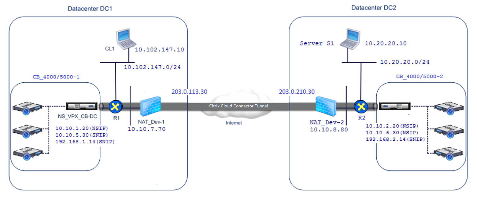
Both CB_ 4000/5000-1 and CB_4000/5000-2 function in one arm mode (WCCP/PBR). They enable communication between private networks in datacenters DC1 and DC2. For example, CB_ 4000/5000-1 and CB_4000/5000-2 enable communication between client CL1 in datacenter DC1 and server S1 in datacenter DC2 through the Citrix Cloud Connector tunnel. Client CL1 and server S1 are on different private networks.
For proper communication between CL1 and S1, L3 mode is enabled on NS_VPX_CB_ 4000/5000-1 and NS_VPX_CB_ 4000/5000-2, and routes are configured as follows:
-
Router R1 has a route for reaching S1 through NS_VPX_CB_ 4000/5000-1.
-
NS_VPX_CB_ 4000/5000_1 has a route for reaching NS_VPX-CB_4000/5000-2 through R1.
-
S1 should have a route reaching CL1 through NS_VPX-CB_4000/5000-2.
-
NS_VPX-CB_ 4000/5000-2 has a route for reaching NS_VPX_CB_4000/5000-1 through R2.
The following table lists the settings on CB_4000/5000-1 in datacenter DC1.
| Entity | Name | Details |
|---|---|---|
| IP address of Client CL1 | 10.102.147.10 | |
| Settings on NAT device NAT-Dev-1 | ||
| NAT IP address on public side | 203.0.113.30* | |
| NAT IP address on private side | 10.10.7.70 | |
| Settings on CB_4000/5000-1 | ||
| Management service IP address of CB_4000/5000-1 | 10.10.1.10 | |
| Settings on NS_VPX_CB_4000/5000-1 running on CB_4000/5000-1 | ||
| The NSIP address | 10.10.1.20 | |
| SNIP address | 10.10.5.30 | |
| Cloud Connector tunnel | Cloud_Connector_DC1-DC2 | Local endpoint IP address of the Citrix Cloud Connector tunnel = 10.10.5.30, Remote endpoint IP address of the Citrix Cloud Connector tunnel = 203.0.210.30* |
| GRE Tunnel Details | ||
| Name = Cloud_Connector_DC1-DC2 | ||
| IPSec Profile Details | ||
| Name = Cloud_Connector_DC1-DC2, Encryption algorithm = AES, Hash algorithm = HMAC SHA1 | ||
| Policy based Route | CBC_DC1_DC2_PBR | Source IP range = Subnet in datacenter1 = 10.102.147.0-10.102.147.255, Destination IP range = Subnet in datacenter2 = 10.20.20.0-10.20.20.255, Next hop type = IP Tunnel, IP tunnel name = CBC_DC1_DC2 |
*These should be public IP addresses.
The following table lists the settings on CB- 4000/5000-2 in datacenter DC2.
| Entity | Name | Details |
|---|---|---|
| IP address of Server S1 | 10.20.20.10 | |
| Settings on NAT device NAT-Dev-2 | ||
| NAT IP address on public side | 203.0.210.30* | |
| NAT IP address on private side | 10.10.8.80 | |
| Settings on CB_4000/5000-2 | ||
| Management service IP address of CB_SDX-1 | 10.10.2.10 | |
| Settings on NS_VPX_CB_4000/5000-2 running on CB_4000/5000-2 | ||
| The NSIP address | 10.10.2.20 | |
| SNIP address | 10.10.6.30 | |
| Citrix Cloud Connector tunnel | Cloud_Connector_DC1-DC2 | Local endpoint IP address of the Citrix Cloud Connector tunnel = 10.10.6.30, Remote endpoint IP address of the Citrix Cloud Connector tunnel = 203.0.113.30* |
| GRE Tunnel Details | ||
| Name = Cloud_Connector_DC1-DC2 | ||
| IPSec Profile Details | ||
| Name = Cloud_Connector_DC1-DC2, Encryption algorithm = AES, Hash algorithm = HMAC SHA1 | ||
| Policy based Route | CBC_DC1_DC2_PBR | Source IP range = Subnet in datacenter2 = 10.20.20.0-10.20.20.255, Destination IP range = Subnet in datacenter1 = 10.102.147.0-10.102.147.255, Next hop type = IP Tunnel, IP tunnel name = CBC_DC1_DC2 |
*These should be public IP addresses.
Following is the traffic flow in the Citrix Cloud Connector tunnel:
-
Client CL1 sends a request to server S1.
-
The request reaches the Citrix virtual appliance NS_VPX_CB_4000/5000-1 running on Citrix SD-WAN WANOP appliance CB_4000/5000-1.
-
NS_VPX_CB_ 4000/5000-1 forwards the packet to one of the SD-WAN WANOP instances running on the Citrix SD-WAN WANOP appliance CB_4000/5000-1 for WAN optimization. After processing the packet, the SD-WAN WANOP instance returns the packet to NS_VPX_CB_4000/5000-1.
-
The request packet matches the condition specified in PBR entity CBC_DC1_DC2_PBR (configured in NS_VPX_CB_4000/5000-1), because the source IP address and the destination IP address of the request packet belong to the source IP range and destination IP range, respectively, set in CBC_DC1_DC2_PBR.
-
Because the tunnel CBC_DC1_DC2_PBR is bound to CBC_DC1_DC2_PBR, the appliance prepares the packet to be sent across the Cloud_Connector_DC1-DC2 tunnel.
-
NS_VPX_CB_ 4000/5000-1 uses the GRE protocol to encapsulate each of the request packets by adding a GRE header and a GRE IP header to the packet. In the GRE IP header, the destination IP address is the address of the cloud connector tunnel (Cloud_Connector_DC1-DC2) end point in datacenter DC2.
-
For Cloud Connector tunnel Cloud_Connector_DC1-DC2, NS_VPX_CB_4000/5000-1 checks the storedIPSec security association (SA) parameters for processing outbound packets, as agreed between NS_VPX_CB_4000/5000-1 and NS_VPX_CB_4000/5000-2. The IPSec Encapsulating Security Payload (ESP) protocol in NS_VPX_CB_4000/5000-1 uses these SA parameters for outbound packets, to encrypt the payload of the GRE encapsulated packet.
-
The ESP protocol ensures the packet’s integrity and confidentiality by using the HMAC hash function and the encryption algorithm specified for the Citrix Cloud Connector tunnel Cloud_Connector_DC1-DC2. The ESP protocol, after encrypting the GRE payload and calculating the HMAC, generates an ESP header and an ESP trailer and inserts them before and at the end of the encrypted GRE payload, respectively.
-
NS_VPX_CB_4000/5000-1 sends the resulting packet NS_VPX_CB_4000/5000-2.
-
NS_VPX_CB_4000/5000-2 checks the stored IPSec security association (SA) parameters for processing inbound packets, as agreed between CB_DC-1 and NS_VPX-AWS for the Cloud Connector tunnel Cloud_Connector_DC1-DC2. The IPSec ESP protocol on NS_VPX_CB_4000/5000-2 uses these SA parameters for inbound packets, and the ESP header of the request packet, to decrypt the packet.
-
NS_VPX_CB_4000/5000-2 then decapsulates the packet by removing the GRE header.
-
NS_VPX_CB_4000/5000-2 forwards the resulting packet to CB_VPX_CB_4000/5000-2, which applies WAN-optimization-related processing to the packet. CB_VPX_CB_4000/5000-2 then returns the resulting packet to NS_VPX_CB_4000/5000-2.
-
The resulting packet is the same one that was received by CB_VPX_CB_4000/5000-2 in step 2. This packet has the destination IP address set to the IP address of server S1. NS_VPX_CB_4000/5000-2 forwards this packet to server S1.
-
S1 processes the request packet and sends out a response packet. The destination IP address in the response packet is the IP address of client CL1, and the source IP address is the IP address of server S1.