Configure link definitions
Link definitions are arranged in an ordered list, one entry per link, which is tested from top to bottom for every packet entering or leaving the appliance. The first matching definition determines which link the packet belongs to. Within each link definition is an ordered list of rules, which is also tested from top to bottom. Each packet is compared to these rules, and if it matches one of them, the packet is considered to be traveling over that link.
Within a single rule, the fields are all ANDed together, so all specified values have to match. All fields default to Any, a wildcard entry that always matches. When a field consists of a list, such as a list of IP subnets, the list entries are ORed together. That is, if any element matches, the list as a whole is considered to be a match.
Links can be based on the Ethernet adapter associated with the traffic, the source and destination IP addresses, VLAN tag, WCCP service group (for WCCP-GRE only), and the source and destination Ethernet MAC address. A simple inline deployment might identify only the LAN-side and WAN-side accelerated bridge ports (apA.1 and apA.2), while a complex datacenter deployment might need to use most of the options provided to disambiguate traffic.
Defining a link in terms of its IP addresses is possible except when redundant links are used. Since a given packet may go over either link in an active-standby or active-active dual-link deployment, some other method must be used to determine which link the packet is using. If dual bridges are used, then the traffic for one link can go over apA and the other over apB, and the links can be defined in terms of adapters. If the two links are served by different routers, the MAC addresses of the routers can be used to tell the traffic apart. When all else fails, WCCP-GRE can be used, and the router can use a different service group for each WAN link, allowing the Citrix SD-WAN WANOP unit to tell the link traffic apart in by service group.
Citrix recommends port based link definitions for simple inline deployments, and IP based link definitions for all other deployments.
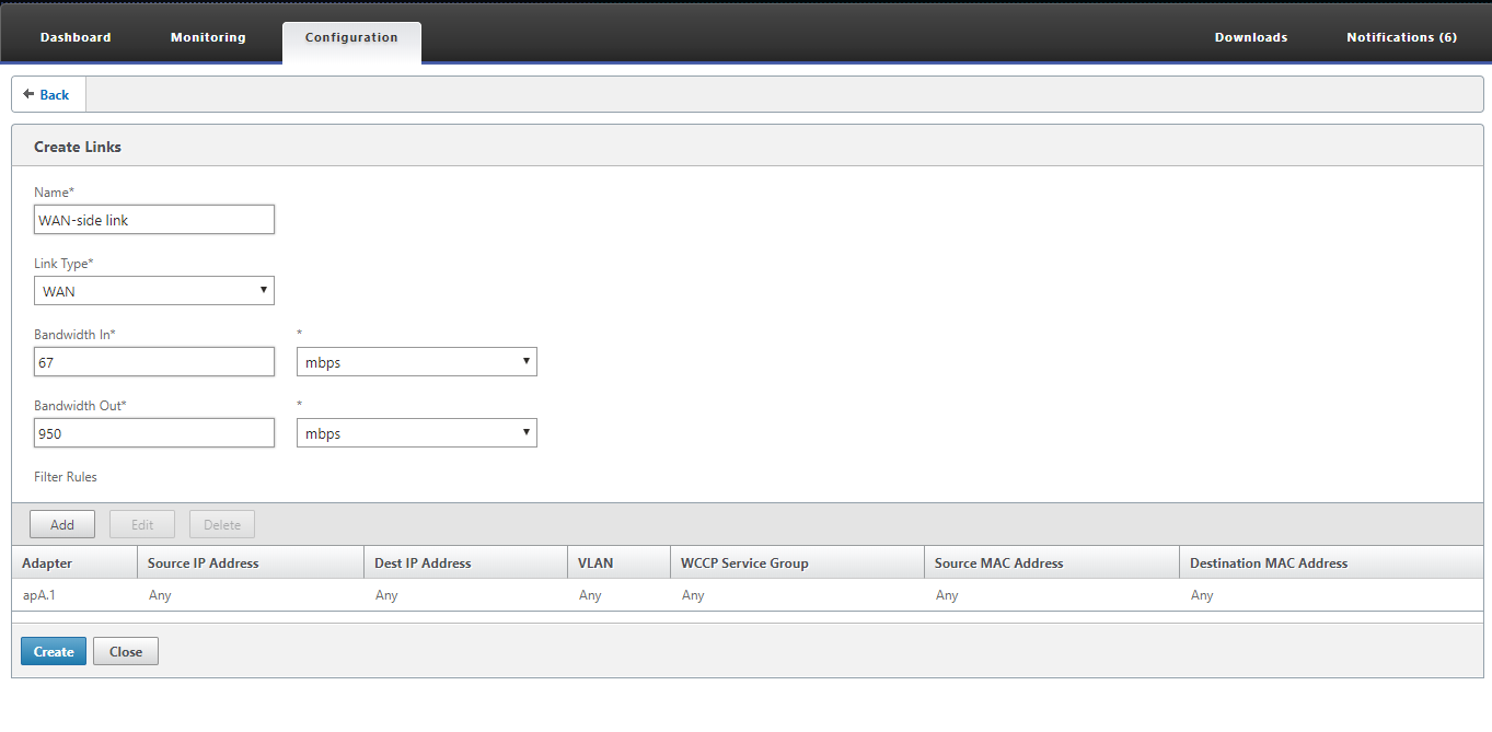
To configure link definitions:
-
Navigate to Configuration > Optimization Rules > Links and click Add.
-
Enter values for the following parameters:
-
Name: A descriptive name of the link, that can also describe if it is a LAN side link or a WAN side link.
-
Link Type: The link type, either LAN or WAN.
-
Bandwidth In: The incoming bandwidth limit.
-
Bandwidth Out: The outgoing bandwidth limit.
-
-
In the Filter Rules section, click Add and enter values for the following parameters:
-
Adapter: This specifies a list of adapters (Ethernet ports). When links can be identified by ethernet adapter, this simplifies configuration.
-
Source IP Address: The Source IP rules are considered for packets entering the unit (packets exiting the unit are ignored). On these packets, the rules in the Src IP field are compared against the Source Address field in the IP header. The rule specifies a list of IP addresses or subnets. Negative matches, such as “Exclude 10.0.0.1” are also supported.
-
Destination IP Address: The Destination IP rules are considered for packets exiting the unit (packets entering the unit are ignored). On these packets, the rules in the Dst IP field are compared against the Destination Address field in the IP header. The rule specifies a list of IP addresses or subnets. Negative matches, such as “Exclude 10.0.0.1” are also supported.
-
VLAN: The VLAN rules are applied to the VLAN headers of packets entering or exiting the unit.
-
WCCP Service Group: The WCCP Service Group rules are applied to GRE-encapsulated WCCP packets entering or leaving the unit. (This does not work with L2 WCCP.)
-
Source MAC Address: The Source MAC address usesd as a filter criteria.
-
Destination MAC Address: The destination MAC address used as a dilter criteria.
-
-
Click Create.
The traffic classifier uses the Src IP and Dest IP fields in a specialized way (the same applies to Src MAC and Dst MAC):
-
The Src field is only examined on packets entering the appliance.
-
The Dst is only examined on packets exiting the appliance.
-
Inline links
Most Citrix SD-WAN WANOP appliances use a simple inline deployment, where each accelerated bridge serves just one WAN link. This is the simplest mode to configure.
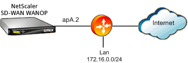
Simple inline link
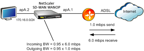
In the above figure , all the traffic passing through the accelerated bridge is assumed to be WAN traffic. The link is an ADSL link with different send and receive speeds (6.0 mbps down, 1.0 mbps up). The WAN is connected to accelerated bridge port apA.1, and the LAN is connected accelerated bridge port apA.2.
The tasks for defining the WAN-side link (apA.1) are:
-
Give the WAN a descriptive name, such as “WAN to HQ (apA.1).”
-
Set the type to “WAN.”
-
Set the incoming and outgoing bandwidth limits to 95% of the nominal link speed.
-
Verify that a rule has been defined that specifies the WAN Ethernet adapter, which in this example is apA.
-
Click Create.
The tasks for the LAN-side link (apA.2) are similar:
-
Give it a descriptive name, such as “Local LAN (apA.2).”
-
Set the type to “LAN.”
-
Set the incoming and outgoing bandwidth limits to 95% of the nominal Ethernet speed (95 mbps or 950 mbps).
-
Verify that a rule exists that specifies the LAN Ethernet adapter, which in this example is apA.2.
-
Click Create.
Inline deployment with dual bridges
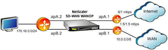
The configuration is similar to the simple inline link configuration, but the site has a second link, a T1 link to the corporate WAN, in addition to the ADSL Internet link. The Citrix SD-WAN WANOP appliance has two accelerated bridges, one for each WAN link.
Configuration is almost as simple as the single-bridge case, with the following additional steps:
-
Edit a second WAN link on apB, which in this case is apB.1. Set the type to “WAN.” Set the link bandwidth to 95% of the 1.5 mbps T1 speed, and give the link a new name, such as “WAN to HQ.”
-
Add a rule specifying apB.2 to the “LAN” definition and delete the default link definition for apB.2. (Alternatively, you can edit the default link definition for apB.2 to specify it as a LAN link, as was done for apA.2.)
Non-inline links
For other than simple inline deployments (which serve only one WAN per accelerated bridge), use IP subnets instead of bridge ports to distinguish LAN traffic from WAN traffic. This approach is essential for one-arm deployments, which use only a single bridge port. IP subnets are sometimes useful for inline deployments as well, especially when the appliance serves more than one WAN. For simple inline deployments, however, port based links are easier to define.
The traffic classifier applies a specialized convention when examining the Src IP and Dst IP:
-
The Src IP field is examined only in packets entering the appliance.
-
The Dst IP field is examined only in packets exiting the appliance.
This convention can sometimes be confusing, but it allows the direction of packet travel to be implicitly considered as part of the definition.
Use IP address in link definitions
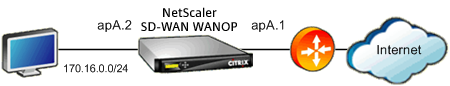
To Configure simple inline LAN definition using IP-based rules, you can define the LAN and WAN links without specifying the Ethernet ports at all, using the LAN subnet instead:
-
Create a rule for the LAN link definition and specify the LAN subnet in the Src IP field.
-
Create a rule for the WAN link definition and specify the LAN subnet (not the WAN subnet) in the Dst IP field.
WCCP and Virtual inline modes
Configuration WCCP or virtual inline deployment using IP based rules is the same as using IP address in link definition, because the LAN and WAN IP subnets are identical.
When WCCP-GRE is used, the GRE headers are ignored and the IP headers within the encapsulated data packets are used. Therefore, this same link definition works for WCCP-L2, WCCP-GRE, inline, and virtual inline modes.
(WCCP and virtual inline modes require configuration of your router. WCCP also requires configuration on the Configuration: Advanced Deployments page.)