OSPF
LAN Side: Dynamic Route Learning
OSPF running on the LAN port of Citrix SD-WAN appliance deployed in Gateway Mode:
Citrix SD-WAN appliances perform route discovery of Layer 3 routing advertisements within a local customer network (both branch and data center) for each of the desired routing protocols (OSPF and BGP). The routes that are learned are dynamically captured and displayed.
This eliminates the need for SD-WAN administrators to statically define the LAN-side networking environment for each appliance that is part of the SD-WAN network.
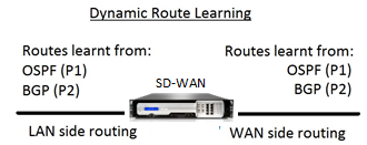
WAN Side: Dynamic Route Sharing
Citrix SD-WAN appliance having an AREA defined as a STUB area by limiting the learning of Type 5 AS-external LSA.
Citrix SD-WAN appliances can advertise the locally learned dynamic routes with the MCN. The MCN can then relay these routes to other SD-WAN appliances in the network. This exchange of information dynamically allows for maintaining connectivity between sites across the changing network.
OSPF Deployment Modes
In previous releases, OSPF instance learned routes from SD-WAN were treated as external routes with Type 5 LSA only. These routes were advertised to its neighbor routers in Type 5 External LSA. This resulted in SD-WAN routes to be less preferred routes according to the OSPF path selection algorithm.
With the latest release, SD-WAN can now advertise routes as intra-area routes (LSA Type 1) to get preference as per its route cost using the OSPF path selection algorithm. The route cost can be configured and advertised to the neighbor router. This allows for deploying the SD-WAN appliance in a one-arm mode described below.
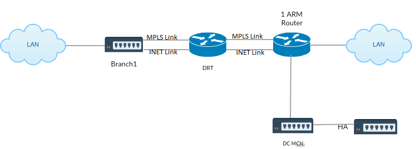
Implementing OSPF in One-Arm Topology
In one-arm configuration, the router needs complicated PBR or WCCP configuration in OSPF deployments. By changing the default export route type from Type 5 to Type 1 we can simplify this deployment. If SD-WAN routes are advertised as intra-area routes with less cost, and the SD-WAN appliance becomes active, the neighbor router selects SD-WAN routes and automatically begins forwarding traffic through the SD-WAN network. Additional PBR or WCCP configuration is not required any longer.
Prerequisites:
- SD-WAN Appliances at the DC and Branch sites must be running the latest release version.
- End-to-End IP connectivity must be configured and working fine.
- OSPF is enabled on all the sites.
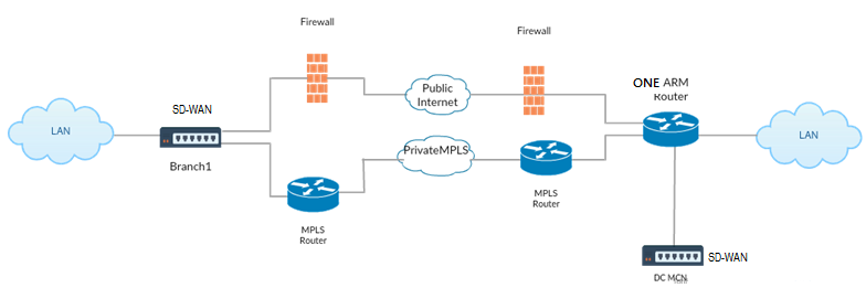
As shown in the illustration above, DC MCN is deployed in one-arm topology. When the DC site is up, the one-arm router forwards all traffic from the local LAN to other sites, such as the Branch’s local LAN whose destination IP address is within the same subnet to the SD-WAN first, then the SD-WAN appliance wraps all packets and sends it to the router with all the packets destination IP address in the Branch Virtual IP address. The router then forwards those packets to WAN.
When the DC site is down, the router forwards all traffic from local LAN to other sites (branch site’s local LAN, destination IP is within subnet) to WAN directly, and not to the SD-WAN appliance.
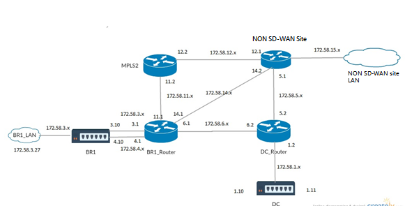
OSPF Type5 to Type1 Deployment in MPLS Network
The following deployment mode is provided to avoid loop formation in an MPLS network configured using SD-WAN appliances. The illustration below describes the standard MPLS network implementation.
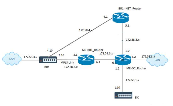
In the above illustration:
- OSPF is configured between ME-BR1_Router and ME-DC_Router in area 0.
- OSPF is configured between ME-DC_Router and DC in area 0.
Recommended Configuration:
-
DC VW and ME-DC_Router on area0
-
ME-BR1_Router and ME-DC_Router on area0
-
BR1 VW and ME-BR1_Router on area0
On the ME-DC_Router:
-
Add, static route for 172.58.3.10/32(Virtual IP of BR1 for MPLS Link) through 172.58.6.1
-
Add, static route for 172.58.4.10/32(Virtual IP of BR1 for INET) through 172.58.5.1
Adding static routes prevents loop formation between the ME-DC_Router and DC SD-WAN appliance. If you do not add static routes, the MCN forwards traffic to the ME-DC Router, and back from the router to the MCN and this creates a loop continuously.
The static routes which are not PBR routes but the destination Host IP based routes traverse towards the right link to be chosen from the DC side based on the path chosen and the encapsulation performed thereafter. Therefore, with these static routes configured, the encapsulated packets with any destination Virtual IP of the BR1 SD-WAN appliance would use these links as per the best path selected by the DC MCN.
Add ACL to avoid loop formation when IPHOST routes are installed (if no static Virtual IPs configured):
-
If the IPHOST routes advertised by the BR1 SD-WAN appliance are installed by the MCN router ME-DC_Router and not added as static routes as mentioned above, there is a possibility of loop formation if the OSPF participating interface (172.58.6.x) between ME-BR1_Router and ME-DC_Router goes down. This is because with this interface down, the IPHOST routes are flushed from ME-DC_Router’s routing table.
-
If this happens, MCN forwards the encapsulated packet destined to one the BR1 VIPs to the ME-DC Router and back from the router to the MCN and loop continuously.
On the ME-BR1_Router:
Advertise 172.58.3.x network to ME-DC_Router with a higher cost than the cost advertised for the same network by DC, if the same AREA-ID is used between ME-BR1_Router <-> ME-DC_Router and ME-DC_Router <-> DC (SD-WAN).
-
Based on the cost metric computation of OSPF 10^8/BW and the cost for route prefixes are based on the interface type. SD-WAN appliances advertise the virtual path and virtual WAN specific static routes to the external or peer routers with the default SD-WAN cost of 5.
-
If the ME-BR1_Router is also advertising 172.58.3.0/24 as an internal OSPF type 1 route alongside DC (SD-WAN) which also advertises the same prefix as an internal OSPF Type 1 route, then according to cost computation, by default the ME-BR1_Router’s route will be configured, as the cost is lesser than SD-WAN’s default cost of 5. To avoid this and make the SD-WAN appliance chosen as the preferred route initially, the interface cost of (172.58.3.1) must be manipulated to make it higher on the ME-BR1_Router so that the DC SD-WAN route is configured in the routing table of the ME-DC_Router.
This also ensures that when the DC SD-WAN appliance fails, the alternate route to use ME-BR1_Router as the next preferred gateway ensures uninterrupted traffic flow.
Use ME-DC_Router as a source for advertising 172.58.8.0/24 network to both DC SD-WAN and the ME-BR1_Router:
With this route, the DC SD-WAN can send packets to the upstream router being aware of the LAN subnet after decapsulation. If DC SD-WAN goes down, the legacy routing infrastructure would help ME-BR1_Router use the ME-DC_Router as the next hop to reach the 172.58.8.x network.
SD-WAN and Third-Party (non-SD-WAN) Appliance Deployment
As shown in the illustration below, the third-party appliance site can get to Site B’s LAN by sending traffic to Site B directly. If it cannot send traffic directly, the fallback route goes to Site A, then using the virtual path between DC to Branch sites to get to the Branch. If that fails, it uses MPLS2 to get to the Branch site.
Traffic flow can be observed in the SD-WAN GUI under Monitoring > Flows.
Implementing OSPF with SD-WAN Network in High Availability Setup
OSPF Type5 to Type1 with high-availability sites during failover to standby appliance and deployed in high-availablity setup:
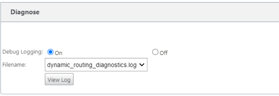
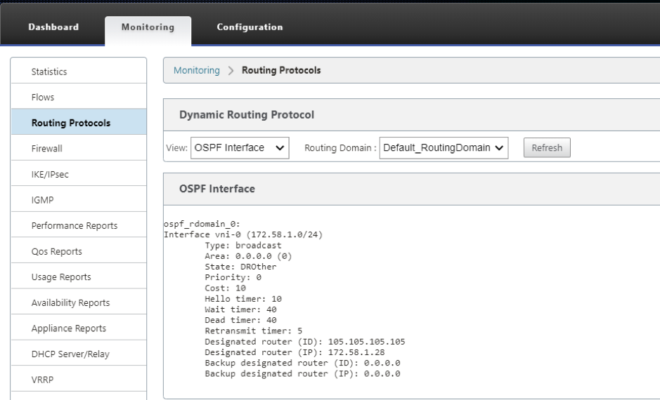
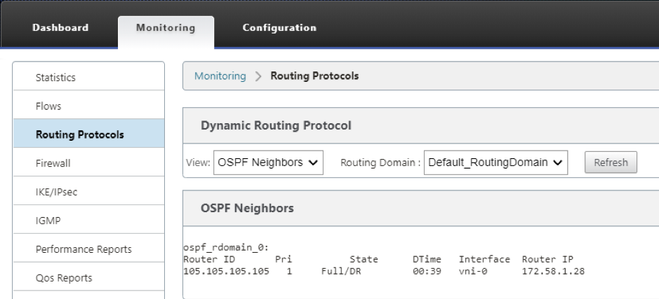
Troubleshooting
You can view the OSPF parameters under Monitoring >Routing Protocols.
You can also observe the Dynamic routing logs to see if there is any issue with OSPF Convergence.