Consolidation with sharing of a physical port by more than one instance
You can enable and disable VLAN filtering on an interface as required. For example, to configure more than 100 VLANs on an instance, assign a dedicated physical interface to that instance and disable VLAN filtering on that interface. Enable VLAN filtering on instances that share a physical interface, so that one instance cannot see the traffic for another instance.
Note: VLAN filtering is not a global setting on the appliance. You enable or disable VLAN filtering on an interface, and the setting applies to all instances associated with that interface. If VLAN filtering is disabled, you can configure up to 4096 VLANs. If VLAN filtering is enabled, you can configure up to 63 tagged VLANs on a 10G interface and up to 32 tagged VLANs on a 1G interface.
In the following example, the instances are part of multiple networks.
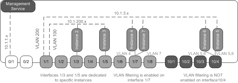
- Interface 1/1 is assigned as a management interface to all the instances. Interface 0/1 is assigned to the Management Service, which is part of the internal 10.1.1.x network.
- Citrix ADC instances 2 and 3 are in the 10.1.200.x network, and instances 4, 5, 6, and 7 are in the 10.1.3.x network. Instances 2 and 3 each have a dedicated physical interface. Instances 4 and 7 share physical interface 1/7, and instances 5 and 6 share physical interface 10/4.
- VLAN filtering is enabled on interface 1/7. Traffic for Instance 4 is tagged for VLAN 4, and traffic for Instance 7 is tagged for VLAN 7. As a result, traffic for Instance 4 is not visible to Instance 7. Conversely, traffic for Instance 7 is not visible to Instance 4. A maximum of 32 VLANs can be configured on interface 1/7.
- VLAN filtering is disabled on interface 10/4, so you can configure up to 4096 VLANs on that interface. Configure VLANs 500–599 on Instance 5 and VLANs 600–699 on Instance 6. Instance 5 can see the broadcast and multicast traffic from VLAN 600–699, but the packets are dropped at the software level. Similarly, Instance 6 can see the broadcast and multicast traffic from VLAN 500–599, but the packets are dropped at the software level.
The following figure illustrates the preceding use case.
Figure 1. Network topology of an SDX appliance with Management Service and Citrix ADC instances distributed across networks
The following table lists the names and values of the parameters used for provisioning Citrix ADC instances 7 and 4 in this example.
| Parameter Name | Values for Instance 7 | Values for Instance 4 |
|---|---|---|
| Name | vpx7 | vpx4 |
| IP Address | 10.1.3.7 | 10.1.3.4 |
| Netmask | 255.255.255.0 | 255.255.255.240 |
| Gateway | 10.1.3.1 | 10.1.3.1 |
| XVA File | NS-VPX-XEN-10.0-51.308.a_nc.xva | NS-VPX-XEN-10.0-51.308.a_nc.xva |
| Feature License | Platinum | Platinum |
| Admin Profile | ns_nsroot_profile | ns_nsroot_profile |
| User Name | vpx4 | vpx4 |
| Password | Sdx1 | Sdx1 |
| Confirm Password | Sdx1 | Sdx1 |
| Shell/Sftp/Scp Access | True | True |
| Total Memory (MB) | 2048 | 2048 |
| #SSL Chips | 1 | 1 |
| Throughput (Mbps) | 1000 | 1000 |
| Packets per second | 1000000 | 1000000 |
| CPU | Shared | Shared |
| Interface | 1/1 and 1/7 | 1/1 and 1/7 |
| NSVLAN | 200 | 200 |
To provision Citrix ADC instances 7 and 4 in this example
- On the Configuration tab, in the navigation pane, expand Citrix ADC Configuration, and then click Instances.
- In the Citrix ADC instances pane, click Add.
- In the Provision Citrix ADC Wizard follow the instructions in the wizard to set the parameters to the values shown in the preceding table.
- Click Create, and then click Close. The Citrix ADC instance you provisioned appears in the Citrix ADC instances pane.