Configuring cluster link aggregation
Cluster link aggregation, as the name suggests, combines a group of cluster-node interfaces into a channel. It is an extension of NetScaler link aggregation (LA). The only difference is that, while link aggregation requires the interfaces to be on the same device, in cluster link aggregation, the interfaces are on different nodes of the cluster. For more information about link aggregation, see Configuring Link Aggregation.
For example, consider a six-node cluster, across two SDX appliances, in which all six nodes are connected to an upstream switch. A cluster LA channel (CLA/1) is formed by binding interfaces 0/1/2, 1/1/3, 2/1/4, 3/1/2, 4/1/3, and 5/1/4.
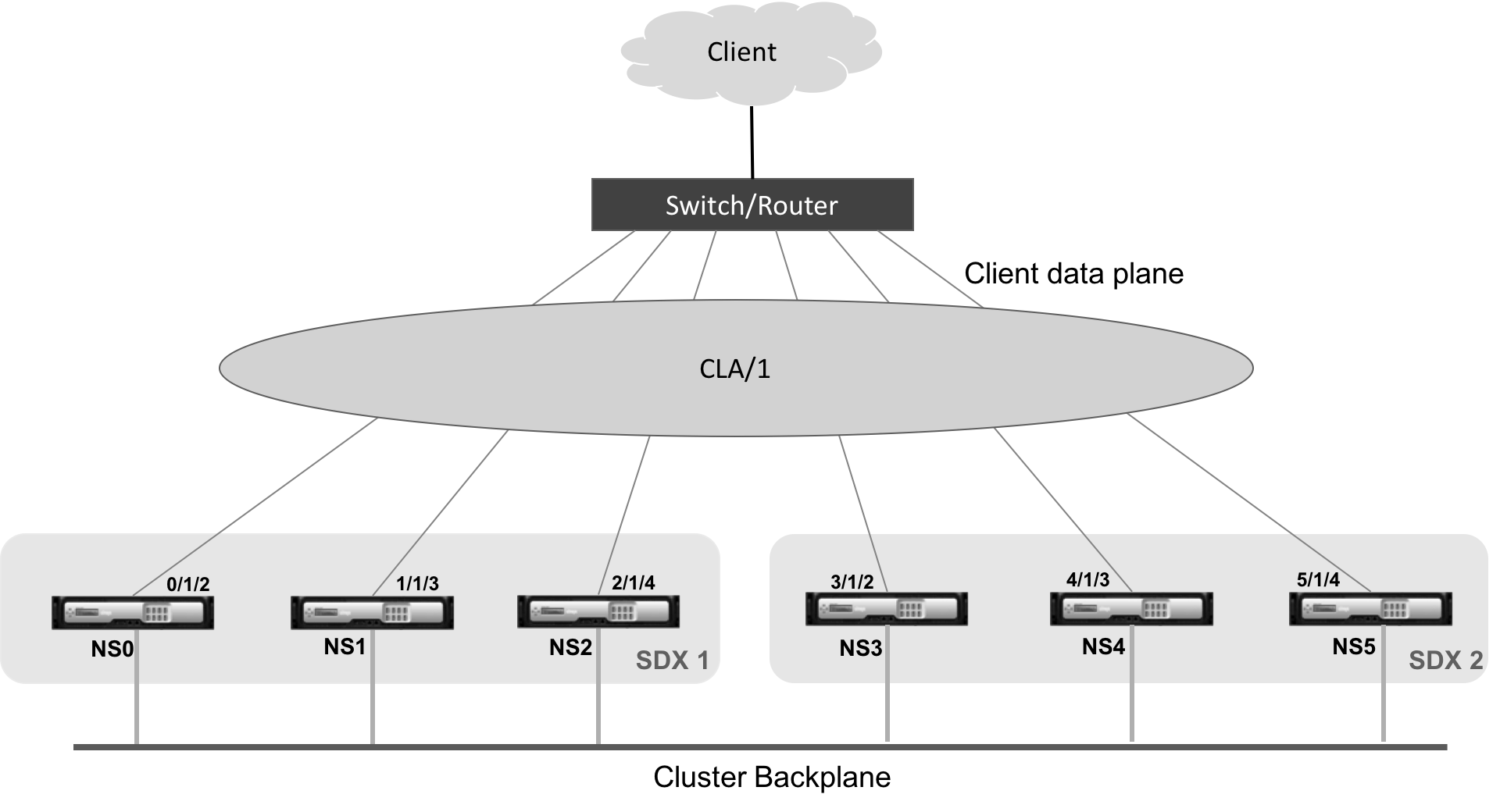
A cluster LA channel has the following attributes:
- Each channel has a unique MAC address agreed upon by cluster nodes.
- The channel can bind both local and remote SDX nodes’ interfaces.
- A maximum of four cluster LA channels are supported in a cluster.
- A maximum of 16 interfaces can be bound to each cluster LA channel.
- Backplane interfaces cannot be part of a cluster LA channel.
- When an interface is bound to a cluster LA channel, the channel parameters take precedence over the network interface parameters.
- A network interface can be bound to only one channel.
- Do not configure management access to a cluster node on a cluster LA channel (for example, CLA/1) or its member interfaces. When the node is INACTIVE, the corresponding cluster LA interface is marked as POWER OFF, which causes it to lose management access.
Implement similar configurations on the cluster IP address and on the external connecting device. If possible, configure the upstream switch to distribute traffic based on the IP address or port instead of the MAC address.
Points to remember:
- Enable LACP (by specifying the LACP mode as either ACTIVE or PASSIVE). Note: Make sure the LACP mode is not set as PASSIVE on both the NetScaler cluster and the external connecting device.
- For creating a cluster LA channel, the LACP key can have a value from 5 through 8. These LACP Keys are mapped to CLA/1, CLA/2, CLA/3, and CLA/4.
- On the SDX appliance, the cluster link aggregation group (CLAG) member interfaces cannot be shared with other virtual machines.
- On the upstream switch, set LACP timeout to “short” to avoid long-duration traffic black holes on cluster nodes. This setting is useful when the upstream switch is not notified of the power down of the CLAG and its member interfaces until after the LACP timeout.
Prerequisites:
Create a cluster of NetScaler instances. The nodes of the cluster can be NetScaler instances on the same SDX appliance or on other SDX appliances that are available on the same subnet.
To configure a cluster LA channel by using the Management Service:
-
Log on to the SDX appliance.
-
On the Configuration tab, navigate to NetScaler, and then click Clusters.
-
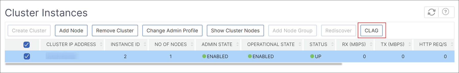
On the Cluster Instances page, select the cluster and click CLAG.
-
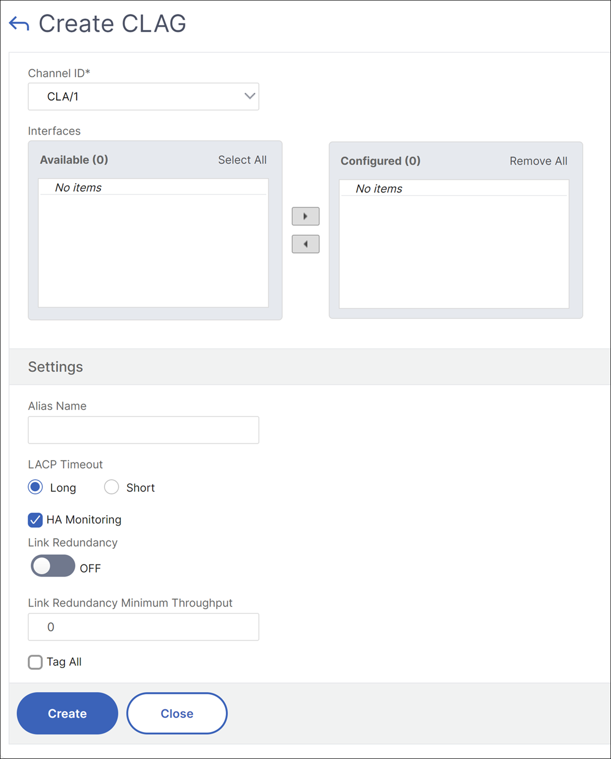
In the Create CLAG dialog box, do the following:
-
In the Channel ID drop-down list, select the cluster LA channel ID.
-
In the Interfaces section, from the Available selection box, select the interfaces and click +.
-
The selected interfaces are displayed under Configured selection box.
-
-
In the Setting section, do the following:
-
In the Alias field, enter an alternative name for the cluster LA channel.
-
In the LACP Timeout field, select one of the following values to define the interval after which a link is not aggregated, if the link does not receive an LACPDU.
The value must match on all the ports participating in link aggregation on the SDX appliance and the partner node:
- Long – 30 seconds
- Short – 1 second
-
For High Availability (HA) configuration, select the HA Monitoring check box to monitor the channel for failure events. Failure of any LA channel that has HA MON enabled triggers HA failover.
-
Select Tag All to add a four-byte 802.1q tag to every packet sent on this channel. The ON setting applies tags for all VLANs that are bound to this channel. OFF applies the tag to all VLANs other than the native VLAN.
-
-
Click Create to configure a CLAG for one of the SDX appliances.
-
In the Confirm dialog box, click Yes to refresh the CLAG settings in the other SDX appliances.
Notes:
- If you select No, the CLAG is not configured.
- Manually refresh the CLAG settings in the other SDX appliances.
- The MTU settings must be the same on both of the SDX appliances. The MTU settings must be changed manually on either of the SDX appliances.
-
To change the MTU settings in the CLAGs dialog box, do the following:
- Select CLA/1 and click Edit.
- In the Configure CLAG dialog box, set the MTU manually in the MTU field and click OK.
-
In the Confirm dialog box, click Yes.