-
Getting Started with Citrix ADC
-
Deploy a Citrix ADC VPX instance
-
Install a Citrix ADC VPX instance on Microsoft Hyper-V servers
-
Install a Citrix ADC VPX instance on Linux-KVM platform
-
Prerequisites for Installing Citrix ADC VPX Virtual Appliances on Linux-KVM Platform
-
Provisioning the Citrix ADC Virtual Appliance by using OpenStack
-
Provisioning the Citrix ADC Virtual Appliance by using the Virtual Machine Manager
-
Configuring Citrix ADC Virtual Appliances to Use SR-IOV Network Interface
-
Configuring Citrix ADC Virtual Appliances to use PCI Passthrough Network Interface
-
Provisioning the Citrix ADC Virtual Appliance by using the virsh Program
-
Provisioning the Citrix ADC Virtual Appliance with SR-IOV, on OpenStack
-
Configuring a Citrix ADC VPX Instance on KVM to Use OVS DPDK-Based Host Interfaces
-
-
Deploy a Citrix ADC VPX instance on Microsoft Azure
-
Network architecture for Citrix ADC VPX instances on Microsoft Azure
-
Configure multiple IP addresses for a Citrix ADC VPX standalone instance
-
Configure a high-availability setup with multiple IP addresses and NICs
-
Configure a high-availability setup with multiple IP addresses and NICs by using PowerShell commands
-
Configure HA-INC nodes by using the Citrix high availability template with Azure ILB
-
Configure address pools (IIP) for a Citrix Gateway appliance
-
-
Upgrade and downgrade a Citrix ADC appliance
-
Solutions for Telecom Service Providers
-
Load Balance Control-Plane Traffic that is based on Diameter, SIP, and SMPP Protocols
-
Provide Subscriber Load Distribution Using GSLB Across Core-Networks of a Telecom Service Provider
-
Authentication, authorization, and auditing application traffic
-
Configuring authentication, authorization, and auditing policies
-
Configuring Authentication, authorization, and auditing with commonly used protocols
-
Use an on-premises Citrix Gateway as the identity provider for Citrix Cloud
-
Troubleshoot authentication issues in Citrix ADC and Citrix Gateway with aaad.debug module
-
-
-
-
-
-
Persistence and persistent connections
-
Advanced load balancing settings
-
Gradually stepping up the load on a new service with virtual server–level slow start
-
Protect applications on protected servers against traffic surges
-
Retrieve location details from user IP address using geolocation database
-
Use source IP address of the client when connecting to the server
-
Use client source IP address for backend communication in a v4-v6 load balancing configuration
-
Set a limit on number of requests per connection to the server
-
Configure automatic state transition based on percentage health of bound services
-
-
Use case 2: Configure rule based persistence based on a name-value pair in a TCP byte stream
-
Use case 3: Configure load balancing in direct server return mode
-
Use case 6: Configure load balancing in DSR mode for IPv6 networks by using the TOS field
-
Use case 7: Configure load balancing in DSR mode by using IP Over IP
-
Use case 10: Load balancing of intrusion detection system servers
-
Use case 11: Isolating network traffic using listen policies
-
Use case 12: Configure Citrix Virtual Desktops for load balancing
-
Use case 13: Configure Citrix Virtual Apps for load balancing
-
Use case 14: ShareFile wizard for load balancing Citrix ShareFile
-
-
-
-
Inline device integration
-
-
Authentication and authorization
-
-
Configuring a CloudBridge Connector Tunnel between two Datacenters
-
Configuring CloudBridge Connector between Datacenter and AWS Cloud
-
Configuring a CloudBridge Connector Tunnel Between a Datacenter and Azure Cloud
-
Configuring CloudBridge Connector Tunnel between Datacenter and SoftLayer Enterprise Cloud
-
Configuring a CloudBridge Connector Tunnel Between a Citrix ADC Appliance and Cisco IOS Device
-
CloudBridge Connector Tunnel Diagnostics and Troubleshooting
This content has been machine translated dynamically.
Dieser Inhalt ist eine maschinelle Übersetzung, die dynamisch erstellt wurde. (Haftungsausschluss)
Cet article a été traduit automatiquement de manière dynamique. (Clause de non responsabilité)
Este artículo lo ha traducido una máquina de forma dinámica. (Aviso legal)
此内容已经过机器动态翻译。 放弃
このコンテンツは動的に機械翻訳されています。免責事項
이 콘텐츠는 동적으로 기계 번역되었습니다. 책임 부인
Este texto foi traduzido automaticamente. (Aviso legal)
Questo contenuto è stato tradotto dinamicamente con traduzione automatica.(Esclusione di responsabilità))
This article has been machine translated.
Dieser Artikel wurde maschinell übersetzt. (Haftungsausschluss)
Ce article a été traduit automatiquement. (Clause de non responsabilité)
Este artículo ha sido traducido automáticamente. (Aviso legal)
この記事は機械翻訳されています.免責事項
이 기사는 기계 번역되었습니다.책임 부인
Este artigo foi traduzido automaticamente.(Aviso legal)
这篇文章已经过机器翻译.放弃
Questo articolo è stato tradotto automaticamente.(Esclusione di responsabilità))
Translation failed!
Inline device integration with Citrix ADC
Security devices such as Intrusion Prevention System (IPS) and Next Generation Firewall (NGFW) protect servers from network attacks. These devices are deployed in layer 2 inline mode and their primary function is to protect servers from network attacks and report security threats on the network. To prevent vulnerable threats and provide advanced security protection, a Citrix ADC appliance is integrated with one or more inline devices. The inline devices can be any security device such as IPS, NGFW. Following are some of the use cases that benefit in using the inline device integration with Citrix ADC appliance:
- Inspecting encrypted traffic. Most IPS and NGFW appliances bypass encrypted traffic, thereby leaving servers vulnerable to attacks. A Citrix ADC appliance can decrypt traffic and send it to inline devices for inspection. This enhances customer’s network security.
- Offloading inline devices from TLS/SSL processing. TLS/SSL processing is expensive and this issue can result in high system CPU in IPS or NGFW appliances if they decrypt the traffic. As encrypted traffic is growing at a fast pace, these systems fail to decrypt and inspect encrypted traffic. Citrix ADC helps in offloading inline devices from TLS/SSL processing. This results in inline device supporting a high volume of traffic inspection.
- Loading balancing inline devices. The Citrix ADC appliance load balances multiple inline devices when there is a high volume of traffic.
- Smart selection of traffic. Every packet flowing into the appliance might be content inspected, for example download of text files. User can configure the Citrix ADC appliance to select specific traffic (for example .exe files) for inspection and send the traffic to inline devices for processing the data
How Citrix ADC is integrated with inline devices
The following diagram shows how a Citrix ADC is integrated with inline security devices.
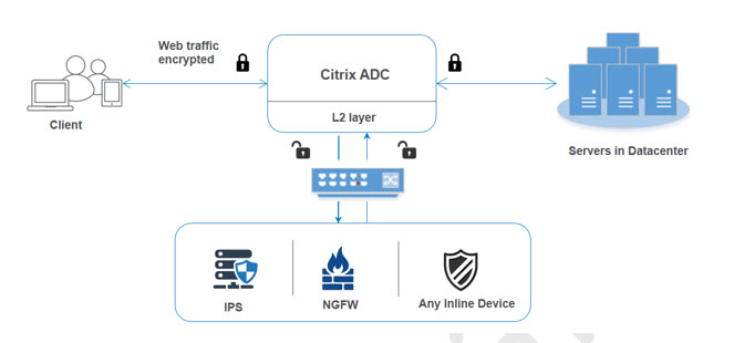
When you integrate inline devices with Citrix ADC appliance, the component interacts as given below:
- A client sends a request to Citrix ADC appliance.
- The appliance receives the request and sends it to an inline device based on policy evaluation. Note: If there are two or more inline devices, the appliance load balances the devices and sends the traffic. If the incoming traffic is an encrypted one, the appliance decrypts the data and sends it as a plain text to the inline device for content inspection.
- The inline device inspects the data for threats and decides whether to drop, reset, or send the data back to the appliance.
- If there are security threats, the device modifies the data and sends it to the appliance.
- The Citrix ADC in turn re-encrypts the data and forwards the request to the back-end server.
- The back-end server sends the response to the Citrix ADC appliance.
- The appliance again decrypts the data and sends it to the inline device for inspection.
- Appliance re-encrypts the data and sends the response to the client
Software licensing
To deploy the inline device integration, your Citrix ADC appliance must be provisioned with one of the licenses given below:
- ADC Premium
- ADC Advanced
- Telco Advanced
- Telco Premium
- SWG license
Configuring inline device integration
You can configure a Citrix ADC appliance with an inline device in three different ways. The configuration scenarios are given below.
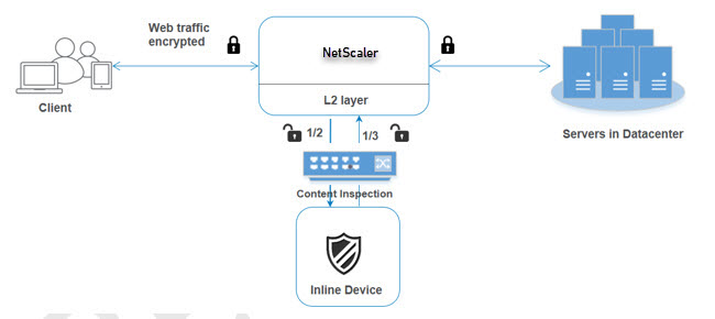
Scenario 1 for using a single inline device
If you want to integrate a security device (IPS or NGFW) in inline mode, you must begin by first enabling the Content Inspection feature and enabling Citrix ADC in MBF (MAC-based forwarding) in global mode. Once you have enabled the features, you must add the Content Inspection profile, add Content Inspection action for inline devices to reset, block, or drop the traffic based on inspection. Then, add the Content Inspection policy for the appliance to decide what subset of traffic to send to the inline devices. Then, configure the load balancing virtual server with layer 2 connection enabled on the server. Finally, bind the content inspection policy to the load balancing virtual server.
Enable MBF (MAC-based forwarding) mode
If you want the Citrix ADC appliance to be integrated to inline devices such as IPS, or firewalls, you must enable this mode. For more information about MBF, see Configure MAC-based Forwarding topic.
At the command prompt, type:
enable ns mode mbf
Enable Content Inspection
If you want Citrix ADC appliance to decrypt and then send the content for inspection to the inline devices, you must enable the Content Inspection and load balancing features.
enable ns feature contentInspection LoadBalancing
Add Content Inspection profile for service
Inline device configuration for a Citrix ADC appliance can be specified in an entity called Content Inspection profile. The profile has a collection of settings that explains how to integrate with an inline device.
At the command prompt, type:
add contentInspection profile <name> -type InlineInspection -egressInterface <interface_name> -ingressInterface <interface_name>[-egressVlan <positive_integer>] [-ingressVlan <positive_integer>]
Example:
add contentInspection profile Inline_profile1 -type InlineInspection -ingressinterface “1/2” -egressInterface “1/3”
Add IPS-TCP monitor
If you want to configure monitors, you first decide whether to use a built-in monitor or add a TCP monitor. Note: If you want to configure monitors, you must use a custom monitor. When adding a monitor, you must enable the transparent parameter.
add lb monitor <monitorName> <type> [-destIP <ip_addr|ipv6_addr>] [-destPort <port>] [-transparent ( YES | NO )]
Example:
add lb monitor ips_tcp TCP -destIP 192.168.10.2 -destPort 80 -transparent YES
Add a service
Add a service. Specify a dummy IP address that is not owned by any of the devices, including the inline devices. Set use source IP address (USIP) to YES. Set useproxyport to NO. By defaut, health monitoring is ON, bind the service to a health monitor, and also set the TRANSPARENT option in the monitor ON.
At the command prompt, type:
add service <Service_name> <IP> TCP * - contentinspectionProfileName <Name> -healthMonitor YES -usip ON –useproxyport OFF
Example:
add service ips_service 198.51.100.2 TCP * -healthMonitor YES -usip YES -useproxyport NO -contentInspectionProfileName ipsprof
Add a health monitor
By default the health monitor is turned on and you also have the option to disable it, if required. At the command prompt, type:
add lb monitor <name> TCP -destIP <ip address> -destPort 80 -transparent <YES, NO>
Example:
add lb monitor ips_tcp TCP -destIP 192.168.10.2 -destPort 80 -transparent YES
Bind the service to the health monitor
After configuring the health monitor, you must bind the service to the health monitor. At the command prompt, type:
bind service <name> -monitorName <name>
Example:
bind service ips_svc -monitorName ips_tcp
Add Content Inspection action for service
After you enable the Content Inspection feature and then after add the inline profile and service, you must add the Content Inspection action for handling the request. Based on the content inspection action, the inline device can drop, reset, or block action after it has inspected the data.
At the command prompt, type:
add contentInspection action <name> -type <type> (-serverName <string> [-ifserverdown <ifserverdown>] [-reqTimeout <positive_integer>] [-reqTimeoutAction <reqTimeoutAction>]
add ContentInspection action < action_name > -type InlineINSPECTION -serverName Service_name/Vserver_name>
Example:
add ContentInspection action <Inline_action> -type InlineSPECTION –serverName Inline_service1
Add content inspection policy for inspection
After you create a Content Inspection action, you must add Content Inspection policies to evaluate requests for inspection. The policy is based on a rule which consists of one or more expressions. The policy evaluates and selects the traffic for inspection based on the rule.
At the command prompt, type the following:
add contentInspection policy <policy_name> –rule <Rule> -action <action_name>
Example
add contentInspection policy Inline_pol1 –rule true –action Inline_action
Add content switching or load balancing virtual server of type HTTP/SSL
To receive the web traffic, you must add a load balancing virtual server. Also you must enable the layer2 connection on the virtual server.
At the command prompt, type:
add lb vserver <name> <vserver name> -l2Conn ON
Example:
add lb vserver HTTP_vserver HTTP 10.102.29.200 8080 –l2Conn ON
Bind Content Inspection policy to content switching virtual server or load balancing virtual server of type HTTP/SSL
You must bind the load balancing virtual server or content switching virtual server of type HTTP/SSL to the Content Inspection policy. At the command prompt, type the following:
bind lb vserver <vserver name> -policyName < policy_name > -priority < priority > -type <REQUEST>
Example:
bind lb vserver HTTP_vserver -policyName Inline_pol1 -priority 100 -type REQUEST
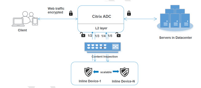
Scenario 2: Load balancing multiple inline devices using dedicated interfaces
If you are using two or more inline devices, you must load balance the devices using different content inspection services in a dedicated VLAN setup. In this case, the Citrix ADC appliance load balances the devices on top of sending a subset of traffic to each device through a dedicated interface. For basic configuration steps, refer to scenario 1.
Add content inspection profile1 for service1
Inline configurations for a Citrix ADC appliance can be specified in an entity called Content Inspection profile. The profile has a collection of device settings. The Content Inspection profile1 is created for inline service 1 and the communication is through 1/2 and 1/3 dedicated interfaces.
At the command prompt, type:
add contentInspection profile <name> -type InlineInspection -egressInterface <interface_name> -ingressInterface <interface_name>[-egressVlan <positive_integer>] [-ingressVlan <positive_integer>]
Example:
add contentInspection profile Inline_profile1 -type InlineInspection -ingressinterface “1/2” -egressInterface “1/3”
Add content inspection profile2 for service2
The Content Inspection profile2 is added for service2 and the inline device communicates with the appliance through 1/4 and 1/5 dedicated interfaces. At the command prompt, type:
add contentInspection profile <name> -type InlineInspection -egressInterface <interface_name> -ingressInterface <interface_name>[-egressVlan <positive_integer>] [-ingressVlan <positive_integer>]
Example:
add contentInspection profile Inline_profile2 -type InlineInspection -ingressinterface “1/4” -egressInterface “1/5”
Add service 1 for inline device 1
After you enable the Content Inspection feature and add the inline profile, you must add an inline service 1 for inline device 1 to be part of the load balancing setup. The service that you add, provides all the inline configuration details.
At the command prompt, type:
add service <Service_name_1> <Pvt_IP1> TCP * -contentInspectionProfileName <Inline_Profile_1> -healthmonitor OFF –usip ON –useproxyport OFF
Example:
add service Inline_service1 10.102.29.200 TCP 80 -contentInspectionProfileName Inline_profile1 -healthmonitor OFF -usip ON -useproxyport OFF
Add service 2 for inline device 2
After you enable the Content Inspection feature and add the inline profile, you must add an inline service 2 for inline device 2. The service that you add, provides all the inline configuration details.
At the command prompt, type:
add service <Service_name_1> <Pvt_IP1> TCP * -contentInspectionProfileName <Inline_Profile_2> -healthmonitor OFF –usip ON –useproxyport OFF
Example:
add service Inline_service1 10.29.20.205 TCP 80 -contentInspectionProfileName Inline_profile2 -healthmonitor OFF -usip ON -useproxyport OFF
Add load balancing virtual server
After you have added the inline profile and the services, you must add a load balancing virtual server for load balancing the services.
At the command prompt, type:
add lb vserver <vserver_name> TCP <Pvt_IP3> <port>
Example:
add lb vserver lb-Inline_vserver TCP *
Bind service 1 to the load balancing virtual server
After you add the load balancing virtual server, now bind the load balancing virtual server to the first service.
At the command prompt, type:
bind lb vserver <Vserver_name> <Service_name_1>
Example:
bind lb vserver lb-Inline_vserver Inline_service1
Bind service 2 to the load balancing virtual server
After you add the load balancing virtual server, now bind the server to the second service.
At the command prompt, type:
bind lb vserver <Vserver_name> <Service_name_1>
Example:
bind lb vserver lb-Inline_vserver Inline_service2
Add content inspection action for the service
After you enable the Content Inspection feature, you must add the Content Inspection action for handling the inline request information. Based on the action selected, the inline device drops, resets, or blocks after it has examined the given subset of traffic.
At the command prompt, type:
add contentInspection action <name> -type <type> (-serverName <string> [-ifserverdown <ifserverdown>] [-reqTimeout <positive_integer>] [-reqTimeoutAction <reqTimeoutAction>]
add ContentInspection action < action_name > -type InlineINSPECTION -serverName Service_name/Vserver_name>
Example:
add ContentInspection action Inline_action -type InlineINSPECTION –serverName lb-Inline_vserver
Add content inspection policy for inspection
After you create a Content Inspection action, you must add Content Inspection policy to evaluate requests for service. The policy is based on a rule which consists of one or more expressions. The rule is associated to the Content Inspection action that is associated if a request matches the rule.
At the command prompt, type the following:
add contentInspection policy <policy_name> –rule <Rule> -action <action_name>
Example:
add contentInspection policy Inline_pol1 –rule true –action Inline_action
Add content switching or load balancing virtual server of type HTTP/SSL
Add a content switching or load balancing virtual server to accept web traffic. Also you must enable the layer2 connection on the virtual server. For more information about load balancing, see How load balancing works topic.
At the command prompt, type:
add lb vserver <name> <vserver name> -l2Conn ON
Example:
add lb vserver http_vserver HTTP 10.102.29.200 8080 –l2Conn ON
Bind Content Inspection policy to load balancing virtual server of type HTTP/SSL
You must bind the content switching or load balancing virtual server of type HTTP/SSL to the Content Inspection policy.
At the command prompt, type the following:
bind lb vserver <vserver name> -policyName < policy_name > -priority <> -type <L7InlineREQUEST | L4Inline-REQUEST>
Example:
bind lb vserver http_vserver -policyName Inline_pol1 -priority 100 -type REQUEST
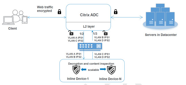
Scenario 3: Load balancing multiple inline devices using shared interfaces
You can refer to this configuration, if you are using multiple inline devices and if you want to load balance the devices using different services in a shared VLAN interface.
This configuration using shared VLAN interfaces is similar to use case 2. For basic configuration, refer to scenario 2.
Bind VLAN A with sharing option enabled
At the command prompt, type the following:
bind vlan <id> -ifnum <interface> -tagged
Example:
bind vlan 100 –ifnum 1/2 tagged
Bind VLAN B with sharing option enabled
At the command prompt, type the following:
bind vlan <id> -ifnum <interface> -tagged
Example:
bind vlan 200 –ifnum 1/3 tagged
Bind VLAN C with sharing option enabled
At the command prompt, type the following:
bind vlan <id> -ifnum <interface> -tagged
Example:
bind vlan 300 –ifnum 1/2 tagged
Bind VLAN D with sharing option enabled
At the command prompt, type the following:
bind vlan <id> -ifnum <interface> -tagged
Example:
bind vlan 400 –ifnum 1/3 tagged
Add content inspection profile1 for service1
Inline configurations for a Citrix ADC appliance can be specified in an entity called Content Inspection profile. The profile has a collection of device settings. The Content Inspection profile1 is created for inline service 1 and the communication is through 1/2 and 1/3 dedicated interfaces.
At the command prompt, type:
add contentInspection profile <name> -type InlineInspection -egressInterface <interface_name> -ingressInterface <interface_name>[-egressVlan <positive_integer>] [-ingressVlan <positive_integer>]
Example:
add contentInspection profile Inline_profile1 -type InlineInspection -ingressinterface “1/2” -egressInterface “1/3” –egressVlan 100 -ingressVlan 300
Add content inspection profile2 for service2
The Content Inspection profile2 is added for service2 and the inline device communicates with the appliance through 1/2 and 1/3 dedicated interfaces.
At the command prompt, type:
add contentInspection profile <name> -type InlineInspection -egressInterface <interface_name> -ingressInterface <interface_name>[-egressVlan <positive_integer>] [-ingressVlan <positive_integer>]
Example:
add contentInspection profile Inline_profile2 -type InlineInspection -ingressinterface “1/2” -egressInterface “1/3” –egressVlan 200 -ingressVlan 400
Configure inline service integration using the Citrix ADC GUI
- Log on to Citrix ADC appliance and navigate to Configuration tab page.
- Navigate to System > Settings > Configure Modes.
- In the Configure Modes page, select Mac Based Forwarding.
- Click OK and Close.
- Navigate to System > Settings > Configure Advanced Features.
- In the Configure Advanced Feature page, select Content Inspection.
- Click OK and Close.
- Navigate to Security > Content Inspection > ContentInspection Profiles.
- In the ContentInspection Profiles page, click Add.
-
In the Create ContentInspection Profiles page, set the following parameters.
- Profile Name. Name of the content inspection profile.
- Type. Select the profile type as inlineInspection.
- Egress Interface. Interface through which the appliance sends traffic from Citrix ADC to the Inline device.
- Ingress Interface. Interface through which the appliance receives traffic from Inline device to Citrix ADC.
- Egress VLAN. Interface VLAN ID through which the traffic is sent to the Inline device.
- Ingress VLAN. Interface VLAN ID through which the appliance receives traffic from Inline to Citrix ADC (if it is configured).
- Click Create and Close.
- Navigate to Traffic Management > Load Balancing > Services and click Add.
-
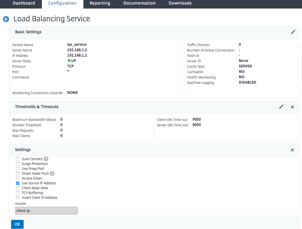
In the Services page, set the following parameters:
- Service name. Name of the load balancing service.
- IP address. Use a dummy IP address. Note: Address should not be owned by any device.
- Protocol. Select protocol type as TCP.
- Port. Enter *
- Health Monitoring. Turn off this option and enable this only if you want to bind the service to TCP type monitor. If you want to bind monitor to service then TRANSPARENT option in monitor should be ON. See step 14 on how to add monitor and how to bind it to service.
- Click OK.
-
In the Settings section, edit the following and click OK.
- Use Proxy Port: Turn it OFF
- Use Source IP Address: Turn it ON
- In the Advanced Settings section, click Profiles.
- Go to Profiles section, and add the inline content inspection profile and click OK.
- Go to Monitors section, Add Bindings> Select Monitor> Add.
- Name: Name of monitor
- Type: Select TCP type
- Destination IP, PORT: Destination IP address and Port.
- Transparent: Turn ON
Note: Monitor packets should flow through inline device to monitor inline device status.
- Click Create.
- Click Done.
- Navigate to Traffic Management > Load Balancing > Virtual Servers. Add a virtual server of type HTTP or SSL.
- After entering the server details, click OK and again OK.
- In the Traffic Settings section of Load Balancing Virtual Server, turn Layer 2 Parameters ON.
- In the Advanced Settings section, click Policies.
- Go the Policies section and click the “+” icon to configure content inspection policy.
- On the Choose Policy page, select Content Inspection. Click Continue.
- In the Policy Binding section, click Add to add a Content Inspection policy.
- In the Create ContentInspection Policy page, enter a name for the Inline content inspection policy.
- In the Action field, click Add to create an Inline content inspection action.
-
In the Create CI Action page, set the following parameters:
- Name. Name of the content inspection Inline policy.
- Type. Select the type as inlineInspection.
- Server. Select the server/service as Inline devices.
- If Server Down. Select an operation if server goes down.
- Request Time-out. Select a time-out value. You can use default values.
- Request Time-out Action. Select a time-out action. You can use default values.
- Click Create.
- In the Create CI Policy page, enter other details:
- Click OK and Close.
This Preview product documentation is Cloud Software Group Confidential.
You agree to hold this documentation confidential pursuant to the terms of your Cloud Software Group Beta/Tech Preview Agreement.
The development, release and timing of any features or functionality described in the Preview documentation remains at our sole discretion and are subject to change without notice or consultation.
The documentation is for informational purposes only and is not a commitment, promise or legal obligation to deliver any material, code or functionality and should not be relied upon in making Cloud Software Group product purchase decisions.
If you do not agree, select I DO NOT AGREE to exit.