- Citrix ADC Release Notes
-
Getting Started with Citrix ADC
- Where Does a Citrix ADC Appliance Fit in the Network?
- How a Citrix ADC Communicates with Clients and Servers
- Introduction to the Citrix ADC Product Line
- Install the hardware
- Access a Citrix ADC
- Configure the ADC for the first time
- Configure high availability
- Configuring a FIPS Appliance for the First Time
- Understanding Common Network Topologies
- System management settings
- Load balance traffic on a Citrix ADC appliance
- Accelerate load balanced traffic by using compression
- Secure load balanced traffic by using SSL
- Features at a Glance
- FAQ
-
Solutions for Telecom Service Providers
-
Large Scale NAT
- Points to Consider before Configuring LSN
- Configuration Steps for LSN
- Sample LSN Configurations
- Configuring Static LSN Maps
- Configuring Application Layer Gateways
- Logging and Monitoring LSN
- STUN Timeout
- TCP SYN Idle Timeout
- Overriding LSN configuration with Load Balancing Configuration
- Clearing LSN Sessions
- Load Balancing SYSLOG Servers
- Port Control Protocol
- LSN44 in a cluster setup
- Dual-Stack Lite
-
Large Scale NAT64
- Points to Consider for Configuring Large Scale NAT64
- Configuring DNS64
- Configuring Large Scaler NAT64
- Configuring Application Layer Gateways for Large Scale NAT64
- Configuring Static Large Scale NAT64 Maps
- Logging and Monitoring Large Scale NAT64
- Port Control Protocol for Large Scale NAT64
- LSN64 in a cluster setup
- Mapping Address and Port using Translation
- Telco subscriber management
- Load Balance Control-Plane Traffic that is based on Diameter, SIP, and SMPP Protocols
- Provide DNS Infrastructure/Traffic Services, such as, Load Balancing, Caching, and Logging for Telecom Service Providers
- Provide Subscriber Load Distribution Using GSLB Across Core-Networks of a Telecom Service Provider
- Bandwidth Utilization Using Cache Redirection Functionality
- Citrix ADC TCP Optimization
- Citrix ADC Video Optimization
- Citrix ADC URL Filtering
-
Large Scale NAT
- Citrix ADC Solutions
-
Deploy a Citrix ADC VPX instance
- Support matrix and usage guidelines
- Install a Citrix ADC VPX instance on XenServer
-
Install a Citrix ADC VPX instance on VMware ESX
- Configuring Citrix ADC Virtual Appliances to use VMXNET3 Network Interface
- Configuring Citrix ADC Virtual Appliances to use Single Root I/O Virtualization (SR-IOV) Network Interface
- Migrating the Citrix ADC VPX from E1000 to SR-IOV or VMXNET3 Network Interfaces
- Configuring Citrix ADC Virtual Appliances to use PCI Passthrough Network Interface
- Install a Citrix ADC VPX instance on Microsoft Hyper-V servers
-
Install a Citrix ADC VPX instance on Linux-KVM platform
- Prerequisites for Installing Citrix ADC VPX Virtual Appliances on Linux-KVM Platform
- Provisioning the Citrix ADC Virtual Appliance by using OpenStack
- Provisioning the Citrix ADC Virtual Appliance by using the Virtual Machine Manager
- Configuring Citrix ADC Virtual Appliances to Use SR-IOV Network Interface
- Configuring Citrix ADC Virtual Appliances to use PCI Passthrough Network Interface
- Provisioning the Citrix ADC Virtual Appliance by using the virsh Program
- Managing the Citrix ADC Guest VMs
- Provisioning the Citrix ADC Virtual Appliance with SR-IOV, on OpenStack
- Configuring a Citrix ADC VPX Instance on KVM to Use OVS DPDK-Based Host Interfaces
-
Deploy a Citrix ADC VPX instance on AWS
- Limitations and usage guidelines
- Prerequisites
- Deploy a Citrix ADC VPX standalone instance on AWS
- Scenario: standalone instance
- Download a Citrix ADC VPX license
- Load balancing servers in different availability zones
- Deploy a high availability pair on AWS
- High availability across AWS availability zones
- Add back-end AWS auto scaling service
- Configure a Citrix ADC VPX instance to use SR-IOV network interface
- Upgrade a Citrix ADC VPX instance on AWS
- Troubleshoot a VPX instance on AWS
-
Deploy a Citrix ADC VPX instance on Microsoft Azure
- Network architecture for Citrix ADC VPX instances on Microsoft Azure
- Configure a Citrix ADC standalone instance
- Configure multiple IP addresses for a Citrix ADC VPX standalone instance
- Configure a high-availability setup with multiple IP addresses and NICs
- Configure a high-availability setup with multiple IP addresses and NICs by using PowerShell commands
- Configure a high-availability setup with a single IP address and a single NIC
- Add Azure autoscale settings
- Configure GSLB on Citrix ADC VPX instances
- Configure GSLB on an ctive-standby high availability setup
- Configure address pools (IIP) for a Citrix Gateway appliance
- Configure multiple IP addresses for a Citrix ADC VPX instance in standalone mode by using PowerShell commands
- Configure multiple Azure VIPs for a standalone or high availability Citrix ADC instance
- Additional PowerShell scripts for Azure deployment
- Azure terminology
- Deploy a Citrix ADC VPX instance on Google Cloud Platform
- Jumbo frames on Citrix ADC VPX instances
- Licensing
- Upgrade and downgrade a Citrix ADC appliance
-
Authentication, authorization, and auditing application traffic
- How Authentication, authorization, and auditing works
- Enabling AAA
- Setting up an authentication virtual server
- Creating an authentication profile
- Configuring users and groups
- Configuring authentication, authorization, and auditing policies
- Self-service password reset
- Authorizing user access to application resources
- Auditing authenticated sessions
- Session settings
- Traffic settings
- Authenticating with client certificates
- Configuring Authentication, authorization, and auditing with commonly used protocols
- Citrix ADC Kerberos single sign-on
- SAML authentication
- OAuth authentication
- Multi-Factor (nFactor) authentication
- Configuring the OpenID Connect Protocol
- Admin Partitioning
-
AppExpert
- Action Analytics
-
AppExpert Applications and Templates
- How AppExpert application works
- Get started with AppExpert
- Customize AppExpert Configuration
- Configure user authentication
- Monitor Citrix ADC statistics
- Delete an AppExpert application
- Configure application authentication, authorization, and auditing
- Set up a custom Citrix ADC application
- Creating and Managing Template Files
- Citrix Gateway Applications
- AppQoE
- Entity Templates
-
HTTP Callouts
- How an HTTP Callout Works
- Notes on the Format of HTTP Requests and Responses
- Configuring an HTTP Callout
- Verifying the Configuration
- Invoking an HTTP Callout
- Avoiding HTTP Callout Recursion
- Caching HTTP Callout Responses
- Use Case: Filtering Clients by Using an IP Blacklist
- Use Case: ESI Support for Fetching and Updating Content Dynamically
- Use Case: Access Control and Authentication
- Use Case: OWA-Based Spam Filtering
- Use Case: Dynamic Content Switching
- Pattern Sets and Data Sets
- Variables
-
Policies and Expressions
- Introduction to Policies and Expressions
- Configuring Advanced Policy Infrastructure
- Configuring Advanced Policy Expression: Getting Started
- Advanced Policy Expressions: Evaluating Text
- Advanced Policy Expressions: Working with Dates, Times, and Numbers
- Advanced Policy Expressions: Parsing HTTP, TCP, and UDP Data
- Advanced Policy Expressions: Parsing SSL Certificates
- Advanced Policy Expressions: IP and MAC Addresses, Throughput, VLAN IDs
- Advanced Policy Expressions: Stream Analytics Functions
- Advanced Policy Expressions: DataStream
- Typecasting Data
- Regular Expressions
- Configuring Classic Policies and Expressions
- Expressions Reference-Advanced Policy Expressions
- Expressions Reference-Classic Expressions
- Summary Examples of Default Syntax Expressions and Policies
- Tutorial Examples of Default Syntax Policies for Rewrite
- Tutorial Examples of Classic Policies
- Migration of Apache mod_rewrite Rules to the Default Syntax
-
Rate Limiting
- Configuring a Stream Selector
- Configuring a Traffic Rate Limit Identifier
- Configuring and Binding a Traffic Rate Policy
- Viewing the Traffic Rate
- Testing a Rate-Based Policy
- Examples of Rate-Based Policies
- Sample Use Cases for Rate-Based Policies
- Rate Limiting for Traffic Domains
- Configure rate limit at packet level
-
Responder
- Enabling the Responder Feature
- Configuring a Responder Action
- Configuring a Responder Policy
- Binding a Responder Policy
- Setting the Default Action for a Responder Policy
- Responder Action and Policy Examples
- Diameter Support for Responder
- RADIUS Support for Responder
- DNS Support for the Responder Feature
- How to Redirect HTTP Requests
- Troubleshooting
-
Rewrite
- How Rewrite Works
- Enabling the Rewrite Feature
- Configuring a Rewrite Action
- Configuring a Rewrite Policy
- Binding a Rewrite Policy
- Configuring Rewrite Policy Labels
- Configuring the Default Rewrite Action
- Bypassing the Safety Check
- Rewrite Action and Policy Examples
- URL Transformation
- RADIUS Support for the Rewrite Feature
- Diameter Support for Rewrite
- DNS Support for the Rewrite Feature
- String Maps
- URL Sets
- AppFlow
-
Application Firewall
- FAQs and Deployment Guide
- Introduction
- Configuring the Application Firewall
-
Signatures
- Manually Configuring the Signatures Feature
- Adding or Removing a Signatures Object
- Configuring or Modifying a Signatures Object
- Protecting JSON Applications using Signatures
- Updating a Signatures Object
- Exporting a Signatures Object to a File
- The Signatures Editor
- Signature Updates in High-Availability Deployment and Build Upgrades
- Overview of Security checks
- Top-Level Protections
- Data Leak Prevention Checks
- Advanced Form Protection Checks
- URL Protection Checks
- XML Protection Checks
- Managing Content Types
- Profiles
- Policy Labels
- Policies
- Imports
- Global Configuration
- Statistics and Reports
- Application Firewall Logs
- Appendices
- Debugging and Troubleshooting
- Signatures Alert Articles
- Cache Redirection
-
Clustering
- Citrix ADC configuration support in a cluster
- Prerequisites for cluster nodes
- Cluster overview
- Setting up a Citrix ADC cluster
- Distributing traffic across cluster nodes
-
Managing the Citrix ADC cluster
- Configuring linksets
- Nodegroups for spotted and partially-striped configurations
- Configuring redundancy for nodegroups
- Disabling steering on the cluster backplane
- Synchronizing cluster configurations
- Synchronizing time across cluster nodes
- Synchronizing cluster files
- Viewing the statistics of a cluster
- Discovering Citrix ADC appliances
- Disabling a cluster node
- Removing a cluster node
- Removing a node from a cluster deployed using cluster link aggregation
- Detecting jumbo probe on a cluster
- Route monitoring for dynamic routes in cluster
- Monitoring cluster setup using SNMP MIB with SNMP link
- Monitoring command propagation failures in a cluster deployment
- Graceful shutdown of nodes
- Graceful shutdown of services
- IPv6 ready logo support for clusters
- Managing cluster heartbeat messages
- Configuring owner node response status
- Monitor Static Route (MSR) support for inactive nodes in a spotted cluster configuration
- VRRP interface binding in a single node active cluster
-
Cluster setup and usage scenarios
- Creating a two-node cluster
- Migrating an HA setup to a cluster setup
- Transitioning between a L2 and L3 cluster
- Setting up GSLB in a cluster
- Using cache redirection in a cluster
- Using L2 mode in a cluster setup
- Using cluster LA channel with linksets
- Backplane on LA channel
- Common interfaces for client and server and dedicated interfaces for backplane
- Common switch for client, server, and backplane
- Common switch for client and server and dedicated switch for backplane
- Different switch for every node
- Sample cluster configurations
- Using VRRP in a cluster setup
- Backup and restore of cluster setup
- Upgrading or downgrading the Citrix ADC cluster
- Operations supported on individual cluster nodes
- Support for heterogeneous cluster
- FAQs
- Troubleshooting the Citrix ADC cluster
- Content Switching
-
DataStream
- Configuring Database Users
- Configuring a Database Profile
- Configuring Load Balancing for DataStream
- Configuring Content Switching for DataStream
- Configuring Monitors for DataStream
- Use Case 1: Configuring DataStream for a Master/Slave Database Architecture
- Use Case 2: Configuring the Token Method of Load Balancing for DataStream
- Use Case 3: Logging MSSQL Transactions in Transparent Mode
- Use Case 4: Database Specific Load Balancing
- DataStream Reference
-
Domain Name System
-
Configure DNS resource records
- Create SRV records for a service
- Create AAAA Records for a domain name
- Create address records for a domain name
- Create MX records for a mail exchange server
- Create NS records for an authoritative server
- Create CNAME records for a subdomain
- Create NAPTR records for telecommunications domain
- Create PTR records for IPv4 and IPv6 addresses
- Create SOA records for authoritative information
- Create TXT records for holding descriptive text
- View DNS statistics
- Configure a DNS zone
- Configure the Citrix ADC as an ADNS server
- Configure the Citrix ADC as a DNS proxy server
- Configure the Citrix ADC as an end resolver
- Configure the Citrix ADC as a forwarder
- Configure Citrix ADC as a non-validating security aware stub-resolver
- Jumbo frames support for DNS to handle responses of large sizes
- Configure DNS logging
- Configure DNS suffixes
- DNS ANY query
- Configure negative caching of DNS records
- Caching of EDNS0 client subnet data when the Citrix ADC appliance is in proxy mode
- Domain name system security extensions
- Support wildcard DNS domains
- Mitigate DNS DDoS attacks
-
Configure DNS resource records
- Firewall Load Balancing
-
Global Server Load Balancing
- GSLB deployment types
- GSLB configuration entities
- GSLB methods
- Configure static proximity
- Configure site-to-site communication
- Configure metrics exchange protocol
- Configure GSLB by using a wizard
- Configure GSLB entities individually
- Synchronize the configuration in a GSLB setup
- GSLB dashboard
- Monitor GSLB services
- Use case: Deployment of domain name based autoscale service group
- Use case: Deployment of IP address based autoscale service group
-
How-to articles
- Customize your GSLB configuration
- Configure persistent connections
- Manage client connections
- Configure GSLB for proximity
- Protect the GSLB setup against failure
- Configure GSLB for disaster recovery
- Override static proximity behavior by configuring preferred locations
- Configure GSLB service selection using content switching
- Configure GSLB for DNS queries with NAPTR records
- Use the EDNS0 client subnet option for GSLB
- Example of a complete parent-child configuration using the metrics exchange protocol
- Link Load Balancing
-
Load Balancing
- How load balancing works
- Set up basic load balancing
- Load balance virtual server and service states
- Support for load balancing profile
- Load balancing algorithms
-
Persistence and persistent connections
- About Persistence
- Source IP address persistence
- HTTP cookie persistence
- SSL session ID persistence
- Diameter AVP number persistence
- Custom server ID persistence
- IP address persistence
- SIP Call ID persistence
- RTSP session ID persistence
- Configure URL passive persistence
- Configure persistence based on user-defined rules
- Configure persistence types that do not require a rule
- Configure backup persistence
- Configure persistence groups
- Share persistent sessions between virtual servers
- Configure RADIUS load balancing with persistence
- View persistence sessions
- Clear persistence sessions
- Override persistence settings for overloaded services
- Troubleshooting
- Customize a load balancing configuration
- Configure diameter load balancing
- Configure FIX load balancing
- Protect a load balancing configuration against failure
- Manage a load balancing setup
-
Manage client traffic
- Configure sessionless load balancing virtual servers
- Redirect HTTP requests to a cache
- Direct requests according to priority
- Direct requests to a custom web page
- Enable cleanup of virtual server connections
- Rewrite ports and protocols for HTTP redirection
- Insert IP address and port of a virtual server in the request header
- Use a specified source IP for backend communication
- Set a time-out value for idle client connections
- Manage RTSP connections
- Manage client traffic on the basis of traffic rate
- Identify a connection with layer 2 parameters
- Configure the prefer direct route option
- Use a source port from a specified port range for backend communication
- Configure source IP persistency for backend communication
- Use IPv6 link local addresses on server side of a load balancing setup
-
Advanced load balancing settings
- Gradually stepping up the load on a new service with virtual server–level slow start
- The no-monitor option for services
- Protect applications on protected servers against traffic surges
- Enable cleanup of virtual server and service connections
- Graceful shutdown of services
- Enable or disable persistence session on TROFS services
- Direct requests to a custom web page
- Enable access to services when down
- Enable TCP buffering of responses
- Enable compression
- Maintain client connection for multiple client requests
- Insert the IP address of the client in the request header
- Retrieve location details from user IP address using geolocation database
- Use source IP address of the client when connecting to the server
- Use client source IP address for backend communication in a v4-v6 load balancing configuration
- Configure the source port for server-side connections
- Set a limit on the number of client connections
- Set a limit on number of requests per connection to the server
- Set a threshold value for the monitors bound to a service
- Set a timeout value for idle client connections
- Set a timeout value for idle server connections
- Set a limit on the bandwidth usage by clients
- Redirect client requests to a cache
- Retain the VLAN identifier for VLAN transparency
- Configure automatic state transition based on percentage health of bound services
-
Built-in monitors
- TCP-based application monitoring
- SSL service monitoring
- FTP service monitoring
- Secure monitoring of servers by using SFTP
- Set SSL parameters on a secure monitor
- SIP service monitoring
- RADIUS service monitoring
- Monitor accounting information delivery from a RADIUS server
- DNS and DNS-TCP service monitoring
- LDAP service monitoring
- MySQL service monitoring
- SNMP service monitoring
- NNTP service monitoring
- POP3 service monitoring
- SMTP service monitoring
- RTSP service monitoring
- XML broker service monitoring
- ARP request monitoring
- XenDesktop Delivery Controller service monitoring
- Web interface service monitoring
- Citrix StoreFront stores monitoring
- Custom monitors
- Configure monitors in a load balancing setup
- Manage a large scale deployment
- Configure load balancing for commonly used protocols
- Use case 1: SMPP load balancing
- Use case 2: Configure rule based persistence based on a name-value pair in a TCP byte stream
- Use case 3: Configure load balancing in direct server return mode
- Use case 4: Configure LINUX servers in DSR mode
- Use case 5: Configure DSR mode when using TOS
- Use case 6: Configure load balancing in DSR mode for IPv6 networks by using the TOS field
- Use case 7: Configure load balancing in DSR mode by using IP Over IP
- Use case 8: Configure load balancing in one-arm mode
- Use case 9: Configure load balancing in the inline mode
- Use case 10: Load balancing of intrusion detection system servers
- Use case 11: Isolating network traffic using listen policies
- Use case 12: Configure XenDesktop for load balancing
- Use case 13: Configure XenApp for load balancing
- Use case 14: ShareFile wizard for load balancing Citrix ShareFile
- Troubleshooting
- Load balancing FAQs
-
Networking
- IP Addressing
-
Interfaces
- Configuring MAC-Based Forwarding
- Configuring Network Interfaces
- Configuring Forwarding Session Rules
- Understanding VLANs
- Configuring a VLAN
- Configuring NSVLAN
- Configuring Allowed VLAN List
- Configuring Bridge Groups
- Configuring VMACs
- Configuring Link Aggregation
- Redundant Interface Set
- Binding an SNIP address to an Interface
- Monitoring the Bridge Table and Changing the Aging time
- Citrix ADC Appliances in Active-Active Mode Using VRRP
- Using the Network Visualizer
- Configuring Link Layer Discovery Protocol
- Jumbo Frames
- Citrix ADC Support for Microsoft Direct Access Deployment
- Access Control Lists
- IP Routing
- Internet Protocol version 6 (IPv6)
- Traffic Domains
- VXLAN
- Priority Load Balancing
-
Citrix ADC Extensions
- Citrix ADC extensions - language overview
- Citrix ADC extensions - library reference
- Citrix ADC extensions API reference
-
Protocol extensions
- Protocol extensions - architecture
- Protocol extensions - traffic pipeline for user defined TCP client and server behaviors
- Protocol extensions - use cases
- Tutorial – Add MQTT protocol to the Citrix ADC appliance by using protocol extensions
- Tutorial - Load balancing syslog messages by using protocol extensions
- Protocol extensions command reference
- Troubleshoot protocol extensions
- Policy extensions
-
Optimization
- Client Keep-Alive
- HTTP Compression
-
Integrated Caching
- Configure selectors and basic content groups
- Configure policies for caching and invalidation
- Cache support for database protocols
- Configure expressions for caching policies and selectors
- Display cached objects and cache statistics
- Improve cache performance
- Configure cookies, headers, and polling
- Configure integrated cache as a forward proxy
- Default Settings for the Integrated Cache
- Troubleshooting
- Front End Optimization
- Content Accelerator
- Media Classification
- Reputation
-
SSL offload and acceleration
- SSL offloading configuration
- TLSv1.3 protocol support as defined in RFC 8446
- How-to articles
- SSL certificates
- SSL profiles
- Certificate revocation lists
- Monitor certificate status with OCSP
- OCSP stapling
- Ciphers available on the Citrix ADC appliances
- Server certificate support matrix on the ADC appliance
- Client authentication
- Server authentication
- SSL actions and policies
- Selective SSL logging
- Support for DTLS protocol
- Support for Intel Coleto SSL chip based platforms
- MPX 9700/10500/12500/15500 FIPS appliances
- MPX 14000 FIPS appliances
-
SDX 14000 FIPS appliances
- Limitations
- Terminology
- Initialize the HSM
- Create partitions
- Provision a new instance or modify an existing instance and assign a partition
- Configure the HSM for an instance on an SDX 14030/14060/14080 FIPS appliance
- Create a FIPS key for an instance on an SDX 14030/14060/14080 FIPS appliance
- Upgrade the FIPS firmware on a VPX instance
- Support for Thales nShield® HSM
- Support for Gemalto SafeNet Network hardware security module
- Troubleshooting
- SSL FAQs
- Global site certificates
- Security
-
System
- Basic operations
- Authentication and authorization
- TCP Configurations
- HTTP Configurations
- SNMP
- Audit Logging
- Web Server Logging
- Call Home
- Reporting Tool
-
CloudBridge Connector
- Monitoring CloudBridge Connector Tunnels
- Configuring a CloudBridge Connector Tunnel between two Datacenters
- Configuring CloudBridge Connector between Datacenter and AWS Cloud
- Configuring a CloudBridge Connector Tunnel Between a Citrix ADC Appliance and Virtual Private Gateway on AWS
- Configuring a CloudBridge Connector Tunnel Between a Datacenter and Azure Cloud
- Configuring CloudBridge Connector Tunnel between Datacenter and SoftLayer Enterprise Cloud
- Configuring a CloudBridge Connector Tunnel Between a Citrix ADC Appliance and Cisco IOS Device
- Configuring a CloudBridge Connector Tunnel Between a Citrix ADC Appliance and Fortinet FortiGate Appliance
- CloudBridge Connector Tunnel Diagnostics and Troubleshooting
- CloudBridge Connector Interoperability – StrongSwan
- CloudBridge Connector Interoperability – F5 BIG-IP
- CloudBridge Connector Interoperability – Cisco ASA
-
High Availability
- Points to Consider for a High Availability Setup
- Configuring High Availability
- Configuring the Communication Intervals
- Configuring Synchronization
- Synchronizing Configuration Files in a High Availability Setup
- Configuring Command Propagation
- Restricting High-Availability Synchronization Traffic to a VLAN
- Configuring Fail-Safe Mode
- Configuring Virtual MAC Addresses
- Configuring High Availability Nodes in Different Subnets
- Configuring Route Monitors
- Limiting Failovers Caused by Route Monitors in non-INC mode
- Configuring Failover Interface Set
- Understanding the Causes of Failover
- Forcing a Node to Fail Over
- Forcing the Secondary Node to Stay Secondary
- Forcing the Primary Node to Stay Primary
- Understanding the High Availability Health Check Computation
- High Availability FAQs
- Troubleshooting High Availability Issues
- Managing High Availability Heartbeat Messages on a Citrix ADC Appliance
- Remove and Replace a Citrix ADC in a High Availability Setup
- TCP Optimization
- Troubleshooting Citrix ADC
- Reference Material
This content has been machine translated dynamically.
Dieser Inhalt ist eine maschinelle Übersetzung, die dynamisch erstellt wurde. (Haftungsausschluss)
Cet article a été traduit automatiquement de manière dynamique. (Clause de non responsabilité)
Este artículo lo ha traducido una máquina de forma dinámica. (Aviso legal)
This content has been machine translated dynamically.
Translation failed!
CloudBridge Connector interoperability – StrongSwan
StrongSwan is an opensource IPSec implementation for Linux platforms. You can configure a CloudBridge Connector tunnel between a Citrix ADC appliance and a StrongSwan appliance to connect two datacenters or extend your network to a cloud provider. The Citrix ADC appliance and the StrongSwan appliance form the end points of the CloudBridge Connector tunnel and are called peers.
Example of a CloudBridge Connector tunnel configuration
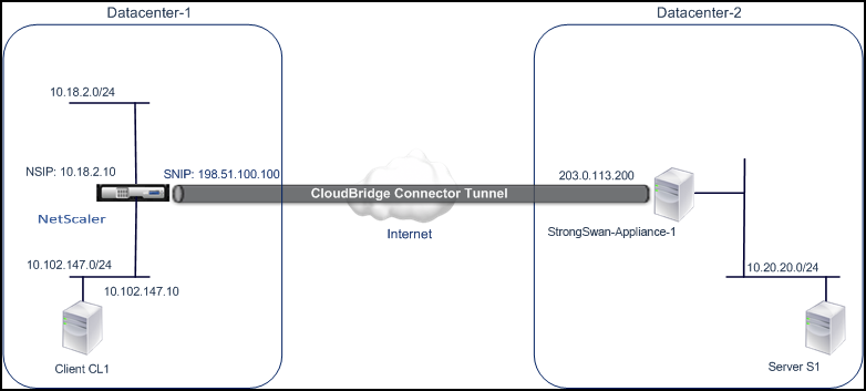
As an illustration of the traffic flow in a CloudBridge Connector tunnel, consider an example in which a CloudBridge Connector tunnel is set up between the following devices:
- Citrix ADC appliance NS_Appliance-1 in a datacenter designated as Datacenter-1
- StrongSwan appliance StrongSwan-Appliance-1 in a datacenter designated as Datacenter-2
NS_Appliance-1 and StrongSwan-Appliance-1 enable communication between private networks in Datacenter-1 and Datacenter-2 through the CloudBridge Connector tunnel. In the example, NS_Appliance-1 and StrongSwan-Appliance-1 enable communication between client CL1 in Datacenter-1 and server S1 in Datacenter-2 through the CloudBridge Connector tunnel. Client CL1 and server S1 are on different private networks.
On NS_Appliance-1, the CloudBridge Connector tunnel configuration includes IPSec profile entity NS_StrongSwan_IPSec_Profile, CloudBridge Connector tunnel entity NS_StrongSwan_Tunnel, and policy based routing (PBR) entity NS_StrongSwan_Pbr.
The following table lists the settings used in this example.
Main settings of the CloudBridge Connector tunnel setup
Entity | Details |
---|---|
IP address of the CloudBridge Connector tunnel end point (NS_Appliance-1) in Datacenter-1 | 198.51.100.100 |
IP address of the CloudBridge Connector tunnel end point (StrongSwan-Appliance-1) in Datacenter-2 | 203.0.113.200 |
Datacenter–1’s subnet whose traffic is to be protected over the CloudBridge Connector tunnel | 10.102.147.0/24 |
Datacenter–2’s subnet whose traffic is to be protected over the CloudBridge Connector tunnel | 10.20.20.0/24 |
Settings on Citrix ADC appliance NS_Appliance-1 in Datacenter-1
SNIP1(for reference purposes only) | 198.51.100.100 | |
---|---|---|
IPSec profile | NS_StrongSwan_IPSec_Profile | IKE version: v1, Encryption algorithm: AES, Hash algorithm: HMAC_SHA1 |
psk = examplepresharedkey (Note: This is an example of a pre-share key, for illustration. Citrix does not recommend to use this string in your CloudBridge Connector configuration) | ||
CloudBridge Connector tunnel | NS_StrongSwan_Tunnel | Remote IP = 203.0.113.200, Local IP= 198.51.100.100, Tunnel protocol = IPSEC, IPSec profile= NS_StrongSwan_IPSec_Profile |
Policy based route | NS_StrongSwan_Pbr | Source IP range = Subnet in the Datacenter-1=10.102.147.0-10.102.147.255, Destination IP range =Subnet in Datacenter-2=10.20.20.0-10.20.20.255, IP Tunnel = NS_StrongSwan_Tunnel |
Points to consider for a CloudBridge Connector tunnel configuration
Before you begin configuring CloudBridge connector tunnel, make sure that:
- You have a basic knowledge about linux configurations.
- You have a basic Knowledge about IPSec protocol suite.
- The StrongSwan appliance is UP and running, is connected to the Internet, and is also connected to the private subnets whose traffic is to be protected over the CloudBridge Connector tunnel.
- The Citrix ADC appliance is UP and running, is connected to the Internet, and is also connected to the private subnets whose traffic is to be protected over the CloudBridge Connector tunnel.
- The following IPSec settings are supported for a CloudBridge Connector tunnel between a Citrix ADC appliance and a StrongSwan appliance.
- IPSec mode: Tunnel mode
- IKE version: Version 1
- IKE authentication method: Pre-Shared Key
- IKE encryption algorithm: AES
- IKE hash algorithm: HMAC SHA1
- ESP encryption algorithm: AES
- ESP hash algorithm: HMAC SHA1
- You must specify the same IPSec settings on the Citrix ADC appliance and the StrongSwan appliance at the two ends of the CloudBridge Connector tunnel.
- Citrix ADC provides a common parameter (in IPSec profiles) for specifying an IKE hash algorithm and an ESP hash algorithm. It also provides another common parameter for specifying an IKE encryption algorithm and an ESP encryption algorithm. Therefore, in the StrongSwan appliance, you must specify the same hash algorithm and same encryption algorithm in IKE and ESP parameters in the IPSec.conf file.
- You must configure the firewall at the Citrix ADC end and StrongSwan end to allow the following.
- Any UDP packets for port 500
- Any UDP packets for port 4500
- Any ESP (IP protocol number 50) packets
Configure StrongSwan for the CloudBridge Connector tunnel
To configure a CloudBridge connector tunnel between a Citrix ADC appliance and a StrongSwan appliance, perform the following tasks on the StrongSwan appliance:
- Specify IPsec connection information in ipsec.conf file. ipsec.conf file defines all control and configuration information for IPsec connections in the strongSwan appliance.
- Specify pre-shared key in ipsec.secrets file. ipsec.secrets file defines secrets for IKE/IPsec authentication for IPsec connections in the strongSwan appliance.
The procedures for configuring IPsec VPN (CloudBridge Connector tunnel) on a StrongSwan appliance might change over time, depending on the StrongSwan release cycle. Citrix recommends that you follow the official StrongSwan documentation for Configuring IPSec VPN tunnels.
Following sample excerpt of ipsec.conf file specifies IPsec information for setting up the IPsec VPN tunnel, described in Example of a CloudBridge Connector Configuration topic. For more information, see CloudBridge Connector Configuration pdf.
Following sample excerpt of ipsec.secrets file specifies the IKE authentication pre-shared key for setting up the IPsec VPN tunnel, described in Example of a CloudBridge Connector Configuration topic.
/etc/ipsec.secrets
-
PSK ‘examplepresharedkey’ #pre-shared key for IPsec IKE authentication`
Configuring the Citrix ADC appliance for the CloudBridge Connector tunnel
To configure a CloudBridge Connector tunnel between a Citrix ADC appliance and a StrongSwan appliance, perform the following tasks on the Citrix ADC appliance. You can use either the Citrix ADC command line or the Citrix ADC graphical user interface (GUI):
- Create an IPSec profile. An IPSec profile entity specifies the IPSec protocol parameters, such as IKE version, encryption algorithm, hash algorithm, and authentication method to be used by the IPSec protocol in the CloudBridge Connector tunnel.
- Create an IP tunnel that uses IPSec protocol, and associate the IPSec profile with it. An IP tunnel specifies the local IP address (CloudBridge Connector tunnel endpoint IP address (of type SNIP) configured on the Citrix ADC appliance), remote IP address (CloudBridge Connector tunnel endpoint IP address configured on the StrongSwan appliance), protocol (IPSec) used to set up the CloudBridge Connector tunnel, and an IPSec profile entity. The created IP tunnel entity is also called the CloudBridge Connector tunnel entity.
- Create a PBR rule and associate it with the IP tunnel. A PBR entity specifies a set of rules and an IP tunnel (CloudBridge Connector tunnel) entity. The source IP address range and the destination IP address range are the conditions for the PBR entity. Set the source IP address range to specify the Citrix ADC-side subnet whose traffic is to be protected over the tunnel, and set the destination IP address range to specify the StrongSwan side subnet whose traffic is to be protected over the tunnel.
To create an IPSEC profile by using the Citrix ADC command line
At the command prompt, type:
add ipsec profile <name> -psk <string> -ikeVersion v1 -encAlgo AES -hashAlgo HMAC_SHA1
show ipsec profile <name>
To create an IPSEC tunnel and bind the IPSEC profile to it by using the Citrix ADC command line
At the command prompt, type:
add ipTunnel <name> <remote> <remoteSubnetMask> <local> -protocol IPSEC –ipsecProfileName <string>
show ipTunnel <name>
To create a PBR rule and bind the IPSEC tunnel to it by using the Citrix ADC command line
At the command prompt, type:
add pbr <pbrName> ALLOW –srcIP <subnet-range> -destIP <subnet-range> -ipTunnel <tunnelName>
apply pbrs
show pbr <pbrName>
To create an IPSEC profile by using the GUI
- Navigate to System > CloudBridge Connector > IPSec Profile.
- In the details pane, click Add.
- In the Add IPSec Profile page, set the following parameters:
- Name
- Encryption Algorithm
- Hash Algorithm
- IKE Protocol Version
- Configure the IPSec authentication method to be used by the two CloudBridge Connector tunnel peers to mutually authenticate: Select the Pre-shared key authentication method and set the Pre-Shared Key Exists parameter.
- Click Create, and then click Close.
To create an IP tunnel and bind the IPSEC profile to it by using the GUI
- Navigate to System > CloudBridge Connector > IP Tunnels.
- On the IPv4 Tunnels tab, click Add.
- In the Add IP Tunnel page, set the following parameters:
- Name
- Remote IP
- Remote Mask
- Local IP Type (In the Local IP Type drop-down list, select Subnet IP).
- Local IP (All the configured IP addresses of the selected IP type are in the Local IP drop-down list. Select the desired IP from the list.)
- Protocol
- IPSec Profile
- Click Create, and then click Close.
To create a PBR rule and bind the IPSEC tunnel to it by using the GUI
- Navigate to System > Network > PBR.
- On the PBR tab, click Add.
- In the Create PBR page, set the following parameters:
- Name
- Action
- Next Hop Type (Select IP Tunnel)
- IP Tunnel Name
- Source IP Low
- Source IP High
- Destination IP Low
- Destination IP High
- Click Create, and then click Close.
The corresponding new CloudBridge Connector tunnel configuration on the Citrix ADC appliance appears in the GUI. The current status of the CloudBridge connector tunnel is shown in the Configured CloudBridge Connector pane. A green dot indicates that the tunnel is up. A red dot indicates that the tunnel is down. The following commands create settings of Citrix ADC appliance NS_Appliance-1 in “Example of a CloudBridge Connector Configuration:
> add ipsec profile NS_StrongSwan_IPSec_Profile -psk examplepresharedkey -ikeVersion v1 –encAlgo AES –hashalgo HMAC_SHA1
Done
> add iptunnel NS_StrongSwan_Tunnel 203.0.113.200 255.255.255.255 198.51.100.100 –protocol IPSEC –ipsecProfileName NS_StrongSwan_IPSec_Profile
Done
> add pbr NS_StrongSwan_Pbr -srcIP 10.102.147.0-10.102.147.255 –destIP 10.20.0.0-10.20.255.255 –ipTunnel NS_StrongSwan_Tunnel
Done
> apply pbrs
Done
Monitoring the CloudBridge Connector tunnel
You can monitor the performance of CloudBridge Connector tunnels on a Citrix ADC appliance by using CloudBridge Connector tunnel statistical counters. For more information about displaying CloudBridge Connector tunnel statistics on a Citrix ADC appliance, see Monitoring CloudBridge Connector Tunnels.