SD-WAN Overlay Routing
Citrix SD-WAN provides resilient and robust connectivity between remote sites, data centers, and cloud networks. The SD-WAN solution can accomplish this by establishing tunnels between SD-WAN appliances in the network enabling connectivity between sites by applying route tables that overlay the existing underlay network. SD-WAN route tables can fully replace or coexist with the existing routing infrastructure.
Citrix SD-WAN appliances measure the paths available unidirectionally in terms of availability, loss, latency, jitter and congestion characteristics, and select the best path on a per-packet basis. This means that the path chosen from Site A to Site B, need not necessarily be the path chosen from Site B to Site A. The best path at a given time is selected independently in each direction. Citrix SD-WAN offers packet-based path selection for rapid adaptation to any network changes. SD-WAN appliances can detect path outages after just two or three missing packets, allowing seamless subsecond failover of application traffic to the next-best WAN path. SD-WAN appliances recalculate every WAN link status in about 50 ms. The following article provides detailed routing configuration within the Citrix SD-WAN network.
Citrix SD-WAN Route Table
The SD-WAN configuration allows static route entries for specific sites, and route entries learned from the underlay network through supported routing protocols; such as OSPF, eBGP, and iBGP. Routes are not only defined by their next hop but by their service type. This determines how the route is forwarded. The following are the main service types in use:
- Local Service: Denotes any route or subnet local to the SD-WAN appliance. This includes the Virtual Interface subnets (automatically creates local routes), and any local route defined in the route table (with a local next hop). The route is advertised to other SD-WAN appliances that have a Virtual Path to this local site where this route is configured when trusted as a partner.
Note
Be cautious when adding default routes, and summary routes as local routes as these can result in virtual path routes at other sites. Always check the route tables to make sure the correct routing is in effect.
-
Virtual Path – Denotes any local route learned from a remote SD-WAN site. That is what is reachable down the virtual paths. These routes are normally automatic, however a virtual path route can be added manually at a site. Any traffic for this route is forwarded to the defined Virtual Path for this destination route (subnet).
-
Intranet – Denotes routes that are reachable through a private WAN link (MPLS, P2P, VPN, and so on). For example, a remote branch that is on the MPLS network but does not have an SD-WAN appliance. It is assumed that these routes must be forwarded to a certain WAN router. Intranet Service is not enabled by default. Any traffic matching this route (subnet) is classified as intranet for this appliance for delivery to a site that does not have an SD-WAN solution.
Note
Notice that when adding an Intranet route there is no next hop, but rather a forward to an Intranet Service. The Service is associated with a given WAN link.
- Internet – This is similar to Intranet but is used to define traffic flowing to public Internet WAN links rather than private WAN links. One unique difference is that the Internet service can be associated with multiple WAN links and set to load balance (per flow) or be active/backup. A default Internet route gets created when internet service is enabled (it is off by default). Any traffic matching this route (subnet) is classified as Internet for this appliance for delivery to public internet resources.
Note
Internet Service routes can be advertised to the other SD-WAN appliances or prevented from being exported depending on whether you are backhauling Internet access over the Virtual Paths.
- Passthrough – This service acts as a last resort or override service when an appliance is in-line mode. If a destination IP address fails to match with any other route, then the SD-WAN appliance simply forwards it onto the WAN link next hop. A default route: 0.0.0.0/0 cost of 16 pass-through route is created automatically. Passthrough does not work when the SD-WAN appliance is deployed out of path or in Edge/Gateway mode. Any traffic matching this route (subnet) is classified as passthrough for this appliance. It is recommended that passthrough traffic is limited as much as possible.
Note
Passthrough can be useful when conducting a POC to avoid having to configure numerous routings, however be careful in production because SD-WAN does not account for WAN link utilization for traffic sent to passthrough. It is also helpful when troubleshooting issues and you want to take a certain IP flow out of delivery over the Virtual Path.
-
Discard - This is not a service but a last resort route that drops the packets if it matches. Normally this does not occur expect when the SD-WAN appliance is deployed out of the path. You must have an Intranet service or local route as a catch all route, otherwise the traffic is discarded as there is no passthrough service (even though a passthrough default route will be present).
The SD-WAN Configuration Editor enables route table customization for each available site:
Route table entries are populated from different inputs:
-
Configured Virtual IP Address (VIP) auto-populate as Service Type Local route. The Configuration Editor prevents the same VIP assignment to different site nodes.
-
Internet Services enabled at a local site auto-populate a default route (0.0.0.0/0) locally for direct internet breakout.
-
Admin defined static routes on a per site basis, which will also be defined as a Service Type Local route.
-
A default (0.0.0.0/0) catches all route with cost 16 defined as Passthrough
Administrators can configure one of the preceding routes, but also include a service type, next hop, or gateway depending on the service type, in addition to route cost. A default route cost will automatically be added to each route type (refer the following table for default route costs). Also, only trusted routes are advertised to other SD-WAN appliances. Untrusted routes are only used by the local appliance.
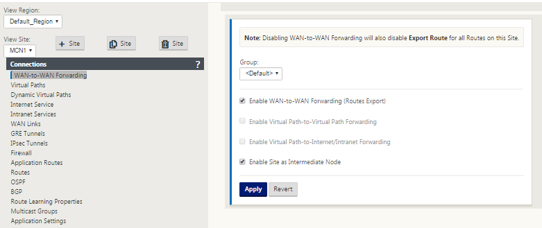
Client node routes are only advertised to the MCN node and no other client nodes by default. For client node routes to be visible to another client nodes WAN to WAN Forwarding must be enabled at the MCN node.
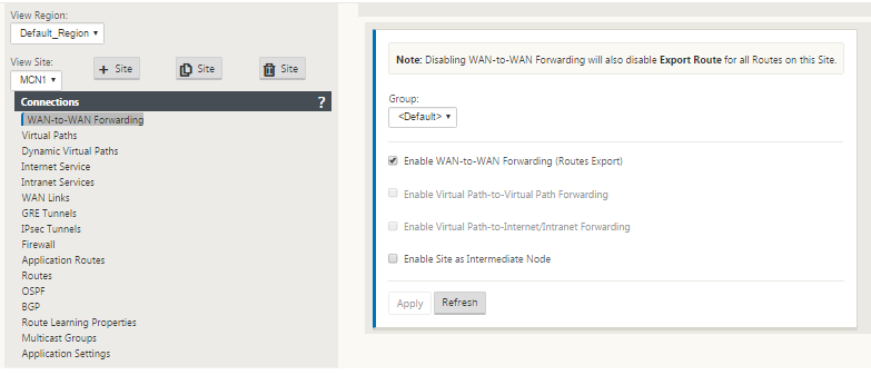
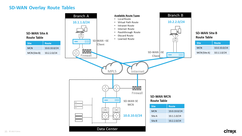
With WAN-to-WAN Forwarding (Routes Export Template) enabled under Global settings, the MCN site shares the advertised routes to all clients participating in the SD-WAN overlay. Turning on this feature enables IP connectivity between hosts at different client node sites with the communication traveling through the MCN. The route table for the local client node can be monitored on the Monitoring > Statistics page with Routes selected for the Show drop-down list.
Each route for remote branch office subnets is advertised as a Service through the Virtual Path connecting through the MCN, with the Site column populated with the client node where the destination resides as a local subnet.
In the following example, with “WAN-to-WAN Forwarding (Routes Export)” enabled, Branch A has a route table entry for the Branch B subnet (10.2.2.0/24) through the MCN as a next hop.
How Citrix SD-WAN Traffic Matches on Defined Routes
The match process for defined routes on Citrix SD-WAN is based on the longest prefix match for the destination subnet (similar to a router operation). The more specific the route, the higher the change on it being matched. Sorting is done in the following order:
- Longest prefix matches
- Cost
- Service
Therefore a /32 route always precedes a /31 route. For two /32 routes, a cost 4 route always precedes a cost 5 route. For two /32 cost 5 routes, routes are chosen based on ordered IP host. Service order is as follows: Local, Virtual Path, Intranet, Internet, Passthrough, Discard.
As an example, consider the following two routes:
-
192.168.1.0/24 Cost 5
-
192.168.1.64/26 Cost 10
A packet destined for the 192.168.1.65 host would use the latter route even though the cost is higher. Based on this, it is common for configuration to be in place for only the routes intended to be delivered over the Virtual Path overlay with other traffic falling into catch all routes such as a default route to the passthrough service.
Routes can be configured in a site node route table that have the same prefix. The tie break then goes to the route cost, the service type (Virtual Path, Intranet, Internet, and so on), and the next hop IP.
Citrix SD-WAN Routing Packet Flow
-
LAN to WAN (Virtual Path) Traffic Route Matching:
-
Incoming traffic is received by the LAN interface and is processed.
-
The received frame is compared to the route table for the longest prefix match.
-
If a match is found, the frame is processed by the rule engine and a flow is created in the flow database.
-
-
WAN to LAN (Virtual Path) Traffic Route Matching:
-
Virtual Path traffic is received by SD-WAN from the tunnel and is processed.
-
The appliance compares the source IP address to see if the source is local.
-
If yes – then WAN eligible and match IP destination to routing table/Virtual Path.
-
If no – then WAN to WAN forwarding enabled check.
-
-
(WAN to WAN Forwarding disabled) Forward to LAN based on local routes.
-
(WAN to WAN Forwarding enabled) Forward to Virtual Path based on route table.
-
-
Non-Virtual Path Traffic:
-
Incoming traffic is received on the LAN interface and is processed.
-
The received frame is compared to the route table for the longest prefix match.
-
If a match is found, the frame is processed by the rule engine and a flow is created in the flow database.
-
Citrix SD-WAN Routing Protocol Support
Citrix SD-WAN release 9.1 introduced OSPF and BGP routing protocols into the configuration. Introducing routing protocols to SD-WAN enabled easier integration of SD-WAN in more complex underlay networks where routing protocols are actively in use. With the same routing protocols enabled on SD-WAN, configuration of subnets denoted to make use of the SD-WAN overlay was made easier. In addition, the routing protocols enable communication between SD-WAN and non-SD-WAN sites with direct communication to existing customer edge routers using the common routing protocol. Citrix SD-WAN participating in routing protocols operating in the underlay network can be done regardless of the deployment mode of SD-WAN (Inline mode, Virtual Inline mode, or Edge/Gateway mode). Also, SD-WAN can be deployed in “learn only” mode where SD-WAN can receive routes but not advertise routes back to the underlay. This is useful when introducing the SD-WAN solution into a network where the routing infrastructure is complex or uncertain.
Important
It is easy to leak the unwanted route, if you are not careful.
The SD-WAN Virtual Path route table works as an External Gateway Protocol (EGP), similar to BGP (think site-to-site). For example, when SD-WAN advertises routes from the SD-WAN appliance to OSPF they are typically considered external to site and protocol.
Note
Be aware of environments that have IGPs across the entire infrastructure (across the WAN) as it does complicate how SD-WAN advertised routes are used. EIGRP is extensively used in the market and SD-WAN does not interoperate with that protocol.
One challenge in introducing Routing Protocols to an SD-WAN deployment is that the route table is not available until the SD-WAN service is enabled and operation in the network, therefore it is not recommended to enable advertise routes from the SD-WAN appliance initially. Use the import and export filters for a gradual introduction of routing protocols on SD-WAN.
Let us take a closer look by reviewing the following example:
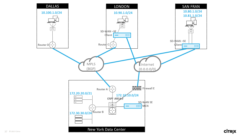
In this example, we examine a routing protocol use case. The preceding network has four locations; New York, Dallas, London, and San Francisco. We deploy SD-WAN appliances at three of these locations, and utilize SD-WAN to create a hybrid WAN network where MPLS and Internet WAN Links will be used to provide a Virtualized WAN. Since Dallas will not have an SD-WAN device, we need to consider how to best integrate with existing route protocols to that site to ensure full connectivity between underlay and SD-WAN overlay networks.
In the example network, eBGP is used between all four locations across the MPLS network. Each location has its own Autonomous System Number (ASN).
In the New York Data Center, OSPF is running to advertise the core Data Center subnets to the remote sites and also announce a default route from the New York Firewall (E). In this example, all internet traffic is backhauled to the data center, even though the London and San Francisco Branches have a path to the internet.
The San Francisco site also must be noted not to have a router. SD-WAN is deployed in Edge/Gateway mode with that appliance being the default gateway for the San Francisco subnet and also participating in eBGP to the MPLS.
- With the New York Data Center, take note that the SD-WAN is deployed in Virtual Inline mode. The intent is to participate in the existing OSPF routing protocol to get traffic forwarded to the appliance as the preferred gateway.
- The London site is deployed in traditional inline mode. The upstream WAN Router (C) will still be the default gateway for the London subnet.
- The San Francisco site is a newly introduced site to this network and the SD-WAN is planned to be deployed in Edge/Gateway mode and act as the default gateway for the new San Francisco subnet.
Review some of the existing underlay route tables before implementing SD-WAN.
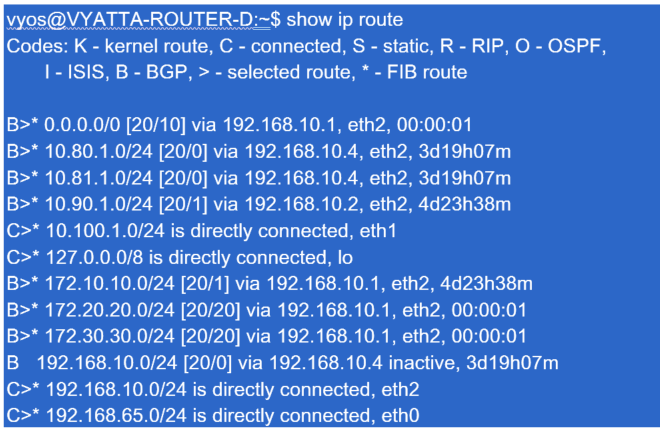
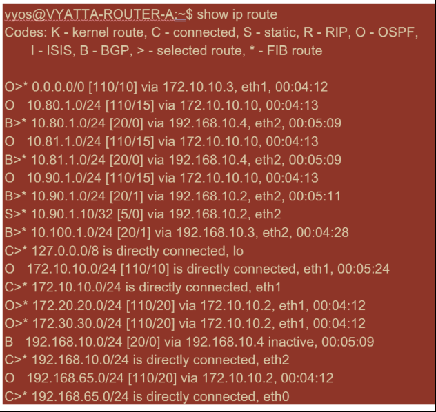
New York Core Router B:
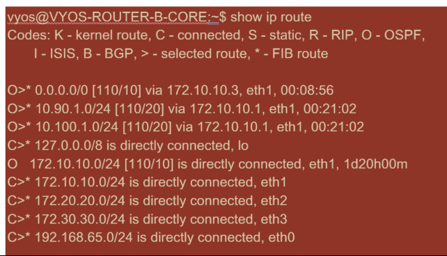
The local New York subnets (172.x.x.x) are available on router B as directly connected, and from the route table we identify that the default route is 172.10.10.3 (Firewall E). Also, we can see that Dallas (10.90.1.0/24) and London (10.100.1.0/24) subnets are available via 172.10.10.1 (MPLS Router A). The route costs indicate that they were learned from eBGP.
Note
In the example provided, San Francisco is not listed as a route, because we have not yet deployed the site with SD-WAN in Edge/Gateway mode for that network.
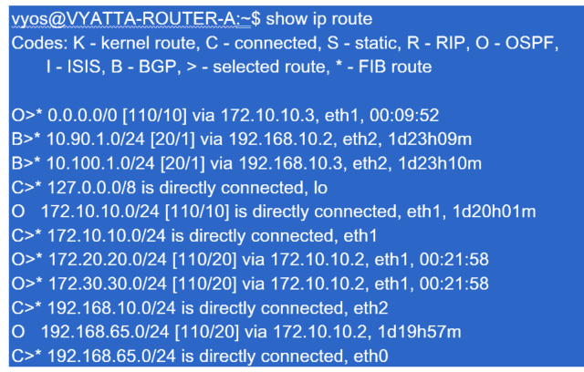
For the New York WAN Router (A), OSPF learned routes and routes learned across the MPLS through eBGP are listed routes. Note the route costs. BGP is lower administrative domain and cost by default 20/1 compared to OSPF 110/10.
Dallas Router D:
For the Dallas WAN Router (D) all routes are learned across the MPLS.
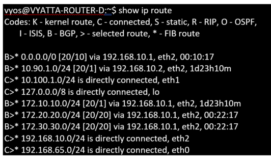
Note
In this example, you can ignore the 192.168.65.0/24 subnet. This is a management network and not pertinent to the example. All the Routers are connected to the management subnet but is not advertised in any routing protocol.
In Citrix SD-WAN, we can add the SD-WAN overlay by enabling OSPF on the SD-WAN located in the New York site under Connections > View Site > OSPF > Basic Settings:
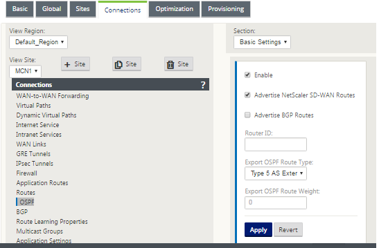
Note
The Export OSPF Route Type is Type 5 External by default. This is because the SD-WAN routing table is considered external to the OSPF protocol and so OSPF will prefer a route learned internal (intra-area), therefore the routes advertised by SD-WAN might not take precedence.
When OSPF is used across the WAN (that is, MPLS networks), then this can be changed to Type one intra-area. OSPF areas can be configured as follows.
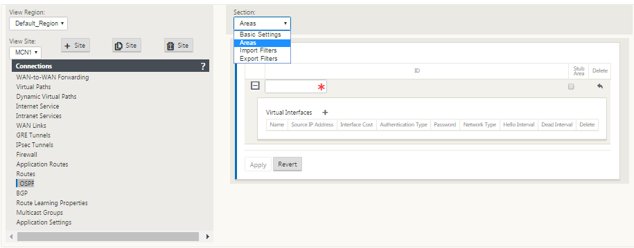
Area 0 added with the local network derived from the Virtual Interface (172.10.10.0), all other settings were left default.
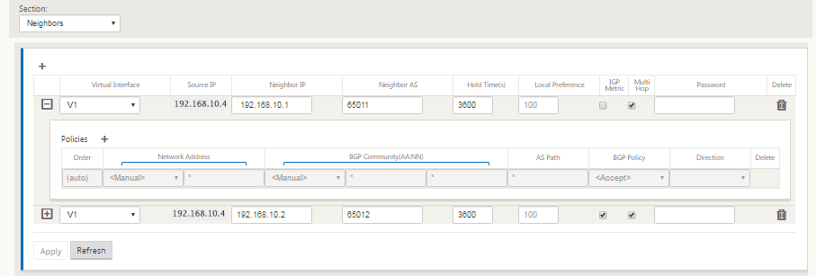
For the new San Francisco site, we need to enable eBGP since it will be directly connected to the MPLS network and operating as the customer edge route for the site. BGP can be enabled under Connections > View Site >BGP > Basic Settings.
Note the Autonomous System number of 13.
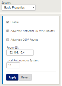
The eBGP peers with each other location. Each ASN is different.
It is important to understand how routes are passed between the Virtual Path routing table and the dynamic route protocols in use. It is easy to create routing loops or advertise routes in an adverse way. The filter mechanism gives us the ability to control what gets into and out of the routing table. We consider each location in turn.
-
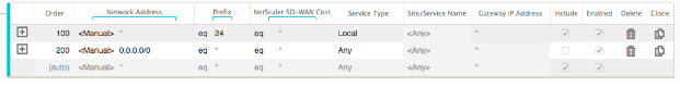
The San Francisco location has two local subnets 10.80.1.0/24 and 10.81.1.0/24. We want to advertise them through eBGP so that sites like Dallas can still reach the San Francisco site over the underlay network and also sites like London and New York can still reach San Francisco over the Virtual Path overlay network. We also want to learn from eBGP reachability to all sites in case the SD-WAN Virtual Path overlay goes down and the environment must fall back to using just the MPLS. We also do not want to readvertise anything SD-WAN learns from eBGP to the SD-WAN routers. To accomplish this, the filters must be configured as follows:
-
Import all routes from eBGP. Do not readvertise/export routes to SD-WAN appliances.
- Export local routes to eBGP
The default rule for export is to export everything. Rule 200 is used to override the fault rule not to readvertise the routes. Any route matching any prefix SD-WAN has learned across the Virtual Paths.
After the Citrix SD-WAN appliances have been deployed, we can take a refreshed look at the route tables for the BGP router at the Dallas site. We see 10.80.1.0/24 and 10.81.1.0/24 subnets are being seen correctly through eBGP from the San Francisco SD-WAN.
Dallas Router D:
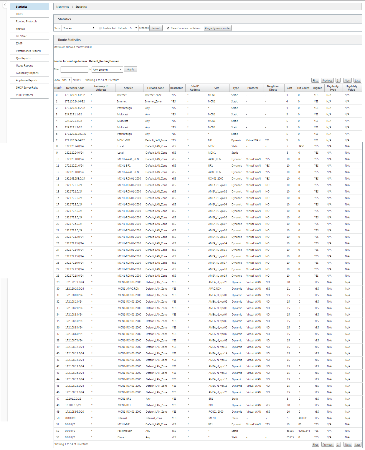
Further, the Citrix SD-WAN route table can be viewed on the Monitoring > Statistics > Show Routes page.
San Francisco Citrix SD-WAN:
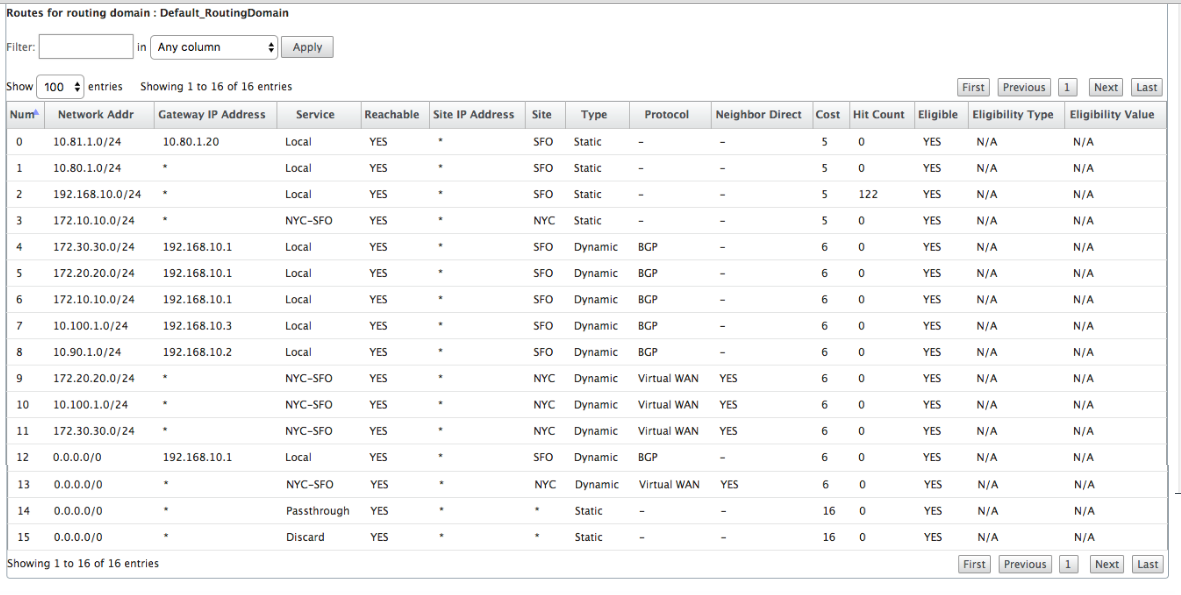
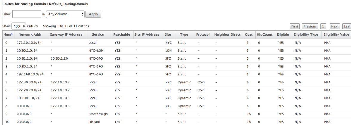
Citrix SD-WAN shows all the routes learned, including routes available through the Virtual Path overlay.
Let us consider 172.10.10.0/24, which is located in the New York Data Center. This route is being learned in two ways:
-
As a Virtual Path route (Number 3), service = NYC-SFO with a cost of 5 and type static. This is a local subnet advertised by SD-WAN appliance in New York. It is static in that it is either directly connected to the appliance or it is a manual static route entered in the configuration. It is reachable because the Virtual Path between the sites is in a working/up state.
-
As an advertised route through BGP (Number 6), with a cost of 6. This is now considered a fallback route.
Since the prefix is equal and the cost is different, SD-WAN uses the Virtual Path route unless it becomes unavailable in which case the fallback route is learned through BGP.
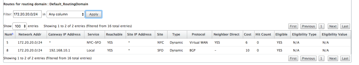
Now, let us consider the route 172.20.20.0/24.
-
This is learned as a Virtual Path route (Number 9) but has a type of dynamic and a cost of 6. This means that the remote SD-WAN appliance learned this route through a routing protocol, in this case OSPF. By default the route cost is higher.
-
SD-WAN also learns this route through BGP with the same cost, so in this case this route might be preferred over the Virtual Path route.
To ensure correct routing, we must increase the BGP route cost to make sure if we have a Virtual Path route and it is the preferred route. This can be done by adjusting the import filter route weight to be higher than the default of 6.
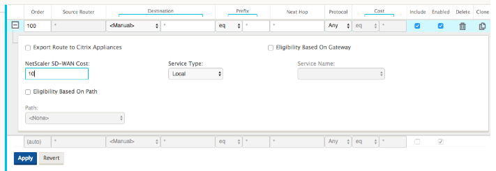
After making the adjustment, we can refresh the SD-WAN route table on the San Francisco appliance to see the adjusted route costs. Use the filter option to focus the displayed list.
Finally, let us look at the learned default route on the San Francisco SD-WAN. We want to backhaul all internet traffic to New York. We can see that we send it using the Virtual Path, if it is up, or through the MPLS network as a fallback.
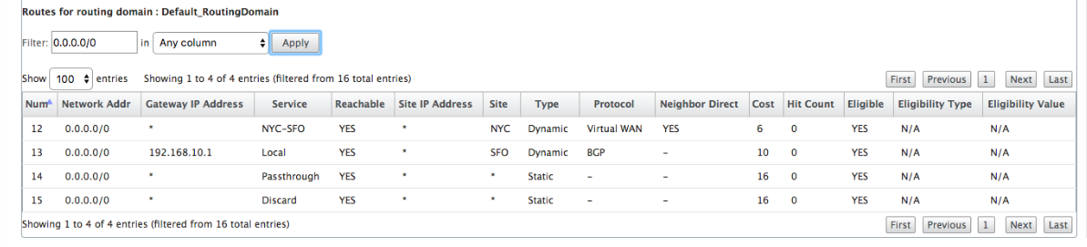
We also see a passthrough and discard route with cost 16. These are automatic routes that cannot be removed. If the device is inline, the passthrough route is used as a last resort so if a packet cannot be matched to a more specific route, SD-WAN will pass it along to the next hop of the interface group. If the SD-WAN is out of path or in edge/gateway mode, there is no passthrough service, in which case SD-WAN drops the packet using the default discard route. The Hit Count indicates the number of packets that are hitting each route, which can be valuable when troubleshooting.
Now focusing on the New York site, we want to get traffic destined for remote sites (London and San Francisco) to be directed to the SD-WAN appliance when the Virtual Path is active.
There are multiple subnets available in the New York site:
-
172.10.10.0/24 (directly connected)
-
172.20.20.0/24 (advertised via OSPF from the core router B)
-
172.30.30.0/24 (advertised via OSPF from the core router B)
We also are required to provide traffic flow to Dallas (10.100.1.0/24) through MPLS.
Lastly, we want all internet bound traffic route to the Firewall E through 172.10.10.3 as a next hop. SD-WAN learns this default route through OSPF and to advertise across the Virtual Path. The filters for the New York site are:
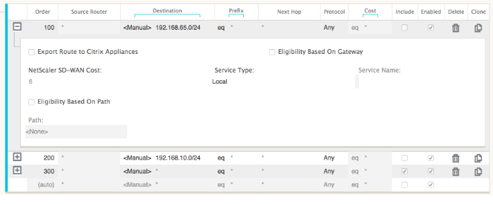
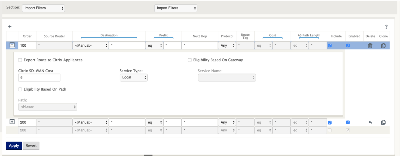
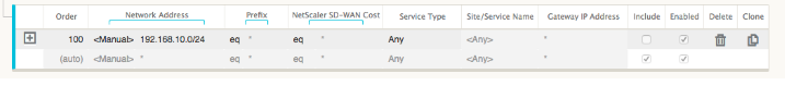
The New York SD-WAN site imports all routes for the management network. This can be ignored. We can focus on filter 200.
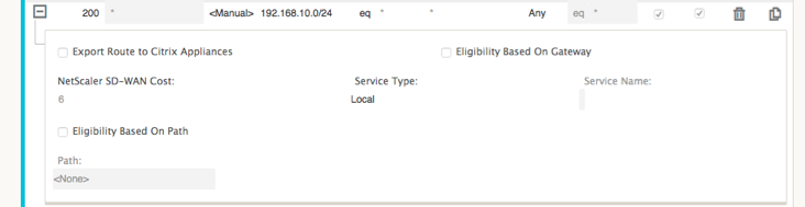
Filter 200 is used to import 192.168.10.0/24 (our MPLS core) for reachability but not to export it to the virtual path. Select the Include check box and ensure that the Export Route to Citrix Appliances check box is cleared. All other routes are then included.
For the export filters, we can exclude the route for 192.168.10.0/24. This is because, as a directly connected subnet in the San Francisco site, we cannot filter this route out at the source, so it is suppressed at this end.
Now let us review the refreshed route table starting at the core route in the New York site.
New York Router B:
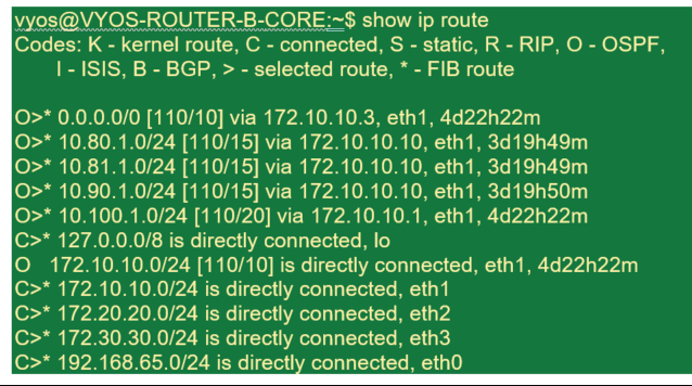
We can see the subnets for San Francisco (10.80.1.0 & 10.81.1.0) and London (10.90.1.0) now being advertised via the New York SD-WAN Appliance (172.10.10.10). The route 10.100.1.0/24 is still being advertised through the underlay MPLS Router A. Let us review the New York site SD-WAN route table.
New York site SD-WAN Route Table:
We can see the correct routes for both the local subnets learned via OSPF, a route to the Dallas site learned from the MPLS Router A and the remote subnets for the San Francisco and London sites. Let us look at the MPLS Router A. This router is participating in OSPF and BGP.
From the route table, this Router A is learning the remote subnets through BGP and OSPF with the Administrative distance and cost of the BGP route (20/5) being lower than OSPF (110/10) and hence preferred. In this example, network where there is only one core route, this might not cause concern. However, traffic arriving here would be delivered via the MPLS network rather than being sent to the SD-WAN Appliance (172.10.10.10). If we want to maintain complete routing symmetry, we would need a route map to adjust the AD/Metric cost so that there is route preference from the route coming from 172.10.10.10 rather than the route learned via eBGP.
Alternatively, a “backdoor” route can be configured to force the router to prefer the OSPF route over the BGP route. Notice the static route for the SD-WAN Virtual IP address to the London site SD-WAN appliance.

This is necessary to ensure that the Virtual Path is rerouted back to the New York site SD-WAN appliance if the MPLS path goes down. Since there is a route for the 10.90.1.0/24 being advertised via 172.10.10.10 (New York SD-WAN). It is also recommended to create an override service rule to drop any UDP 4,980 packets at the SD-WAN appliance to prevent the Virtual Path from coming back to itself.
Dynamic Virtual Paths
Dynamic Virtual Paths can be allowed between two client nodes to build on-demand virtual paths for direct communication between the two sites. The advantage of a dynamic virtual path is that traffic can flow directly from one client node to the second without having to traverse the MCN or two virtual paths, which could add latency to the traffic flow. Dynamic virtual paths are built and removed dynamically based on user-defined traffic thresholds. These thresholds are defined as either packets per second (pps) or bandwidth (kbps). This functionality enables a dynamic full mesh SD-WAN overlay topology.
Once the thresholds for dynamic virtual paths are met, the client nodes dynamically create their virtualized path to one another using all available WAN paths between the sites and make full use of it in the following manner:
-
Send Bulk data if any exists and verify no loss, then
-
Send Interactive data and verify no loss, then
-
Send Real Time data after the Bulk and Interactive data are considered stable (no loss or acceptable levels)
-
If there is no Bulk or interactive data send Real Time Data after the Dynamic Virtual Path has been stable for a period
-
If the user data falls below the configured thresholds for a user defined period, the dynamic virtual path is torn down
Dynamic Virtual Paths have the concept of an Intermediate site. The intermediate site can be an MCN site or any other site in the network that has Static Virtual Path configured and connected to two or more other client nodes. Another design consideration requirement is to have WAN-to-WAN Forwarding enabled, allowing all routes from all sites to be advertised to the client nodes where the dynamic virtual path is desired. “Enable Site as Intermediate Node” must be enabled in addition to WAN-to-WAN Forwarding for this intermediate site to monitor client node communication and to dictate when the dynamic path must be established and torn down.
Multiple WAN-to-WAN Forwarding Groups can are allowed in the SD-WAN configuration, enabling full control to path establishment between certain client nodes and not others.
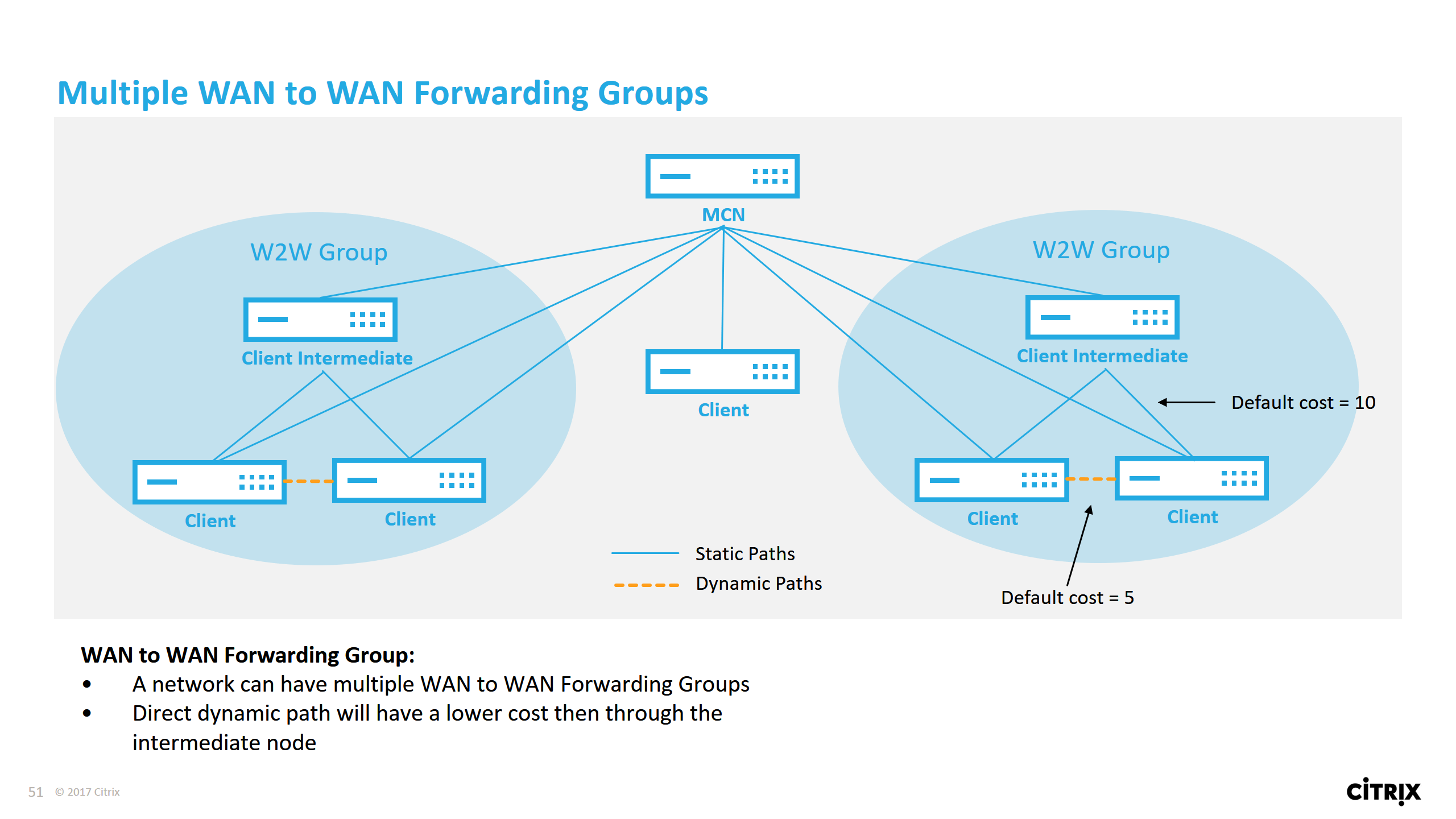
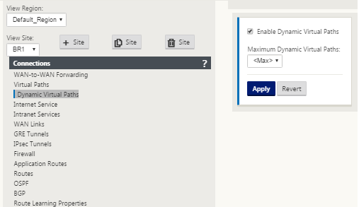
For client nodes to operate as Intermediate sites, a static Virtual Path is required to be configured between it and the clients that are associated with that WAN-to-WAN Forwarding Group. In addition, client nodes need Enable Dynamic Virtual Path option turned on for each client node.
Each SD-WAN device has its own unique route table with the following details defined for each route:
-
Num – order of route of this appliance based on match process (lowest Num processed first)
-
Network address – subnet or host address
-
Gateway if necessary
-
Service – what service is applied for this route
-
Firewall Zone – the firewall zone classification of the route
-
Reachable – Identifies if the Virtual Path state is active for this site
-
Site – The name of the site where the route is expected to exist
-
Type – Identification of route type (Static or Dynamic)
-
Neighbor Direct
-
Cost - cost of the specific route
-
Hit Count – how many times the route has been used per packet. This would be used to verify that a route is being hit correctly.
-
Eligible
-
Eligibility Type
-
Eligibility Value
The following is an example SD-WAN site route table:
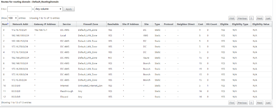
Notice from the preceding SD-WAN route table that there are more elements not normally available in traditional routers. Most notable is the “Reachable” column, which renders the route either active or inactive (yes/no) depending on the WAN path state. Routes listed here are suppressed based on various states of the service (the Virtual Path being down as an example). Other events that can force a route to be ineligible are path down state, next hop unreachable, or WAN link down.
From the preceding table, we can see 14 defined routes. A description of the routes or groups of routes is described as follows:
-
Route 0 – On the MCN this is a Host subnet route that resides at the DC site. 172.16.10.0/24 resides in the DC LAN and 192.168.15.1 is the gateway on the LAN that is the next hop that will get to that subnet.
-
Route 1 – This is a local route to this SD-WAN device that displaying the route table.
-
Route 2–4 – These are the subnets that are part of the virtual interfaces configured for the DC site SD-WAN. These subnets are derived from the trusted virtual interfaces defined.
-
Route 5 – This is a shared route to another client node that is shared by the MCN with a Reachability status of No due to the down Virtual Path between that site and the MCN.
-
Route 6–9 – These routes exist at another client site. For this route, a Virtual Path route is created for matching WAN ingress traffic destined for the remote site on the Virtual Path.
-
Route 10 – With the Internet Service defined, the system adds a catch all route for direct internet breakout for this local site.
-
Route 11 – Passthrough is the default route the system always adds to allow packets to flow through in case there is no match on any existing routes. The Passthrough is not groomed, typically local broadcasts and ARP traffic are mapped to this service.
-
Route 12 – Discard is the default route the system always adds to drop anything undefined.
Default Route Cost Values:
-
WAN to WAN Forwarding – 10
-
Default Direct Route Cost – 5
-
Auto Generated Routes – 5
-
Virtual Path – 5
-
Local – 5
-
Intranet – 5
-
Internet – 5
-
Passthrough – 5
-
Optional – route is 0.0.0.0/0 defined as a service level
After defining these routes, it is important to understand how the traffic flows using the defined routes. These traffic flows are broken into the following flows:
-
LAN to WAN (Virtual Path) – Traffic going into the SD-WAN overlay tunnel
-
WAN to LAN (Virtual Path) – Traffic existing the SD-WAN overlay tunnel
-
Non-Virtual Path Traffic – Traffic routed to the underlay network
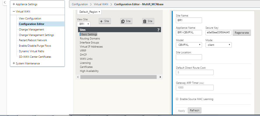
The default route cost can be altered on a per-site basis. The configuration can be found under View Site > Basic Settings:
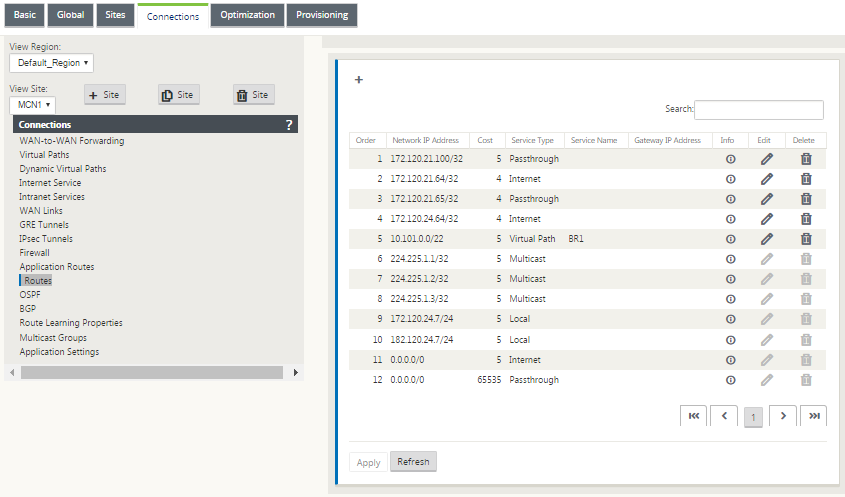
Static routes can be defined per site under the Connections > Site > Routes node:
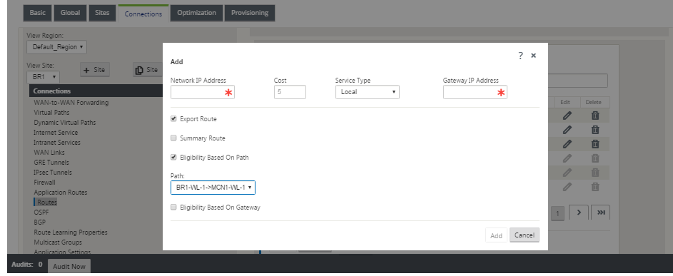
You notice that routes can be tied to the Virtual Path or Gateway IP availability. Internet routes can be exported to the Virtual Path overlay or not depending on desired behavior. You can also create static Virtual Path routes to force traffic to a Virtual Path even though we are not getting the prefix advertised to SD-WAN (that is, a higher cost route of last resort). SD-WAN can also suppress local subnets from being advertised by making the Virtual IP Address (VIP) private.
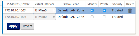
Note
The configuration does require at least one non-private VIP in each route domain.
Intranet and Internet Routes
For the Intranet and Internet service types, the user must have defined an SD-WAN WAN Link to support those types of services. It is a pre-requisite for any defined routes for either of these services. If the WAN link is not defined to support the Intranet Service, it is considered as a local route. The Intranet, Internet, and Passthrough routes are only relevant to the site/appliance they are configured for.
When defining Intranet, Internet or Passthrough routes the following are design considerations:
-
Must have service defined on the WAN link (Intranet/Internet – required)
-
Intranet/Internet must have gateway defined for the WAN link
-
Relevant to local SD-WAN device
-
Intranet routes can be learned via the Virtual Path but are done so at a higher cost
-
With Internet Service, there is automatically a default route created (0.0.0.0/0) catch all route with a max cost
-
Do no assume that Passthrough works, it must be tested/verified, also test with Virtual Path down/disabled to verify desired behavior
-
Route tables are static unless the route learning feature is enabled
The following is the maximum supported limit for multiple routing parameters:
-
Maximum Routing Domains: 255
-
Maximum Access Interfaces per WAN Link: 64
-
Maximum BGP neighbors per site: 255
-
Maximum OSPF area per site: 255
-
Maximum Virtual Interfaces per OSPF area: 255
-
Maximum Route Learning import filters per site: 512
-
Maximum Route Learning export filters per site: 512
-
Maximum BGP routing policies: 255
-
Maximum BGP community string objects: 255