Gateway mode
Gateway mode places the SD-WAN appliance physically in the path (two-arm deployment) and requires changes in the existing network infrastructure to make the SD-WAN appliance the default gateway for the entire LAN network for that site. Gateway mode used for new networks and router replacement. Gateway mode allows SD-WAN appliances:
- To view all traffic to and from the WAN
- To perform local routing
Note
An SD-WAN deployed in Gateway mode acts as a Layer 3 device and cannot perform fail-to-wire. All interfaces involved will be configured for Fail-to-block. In the event of appliance failure, the default gateway for the site will also fail, causing an outage until the appliance and default gateway are restored.
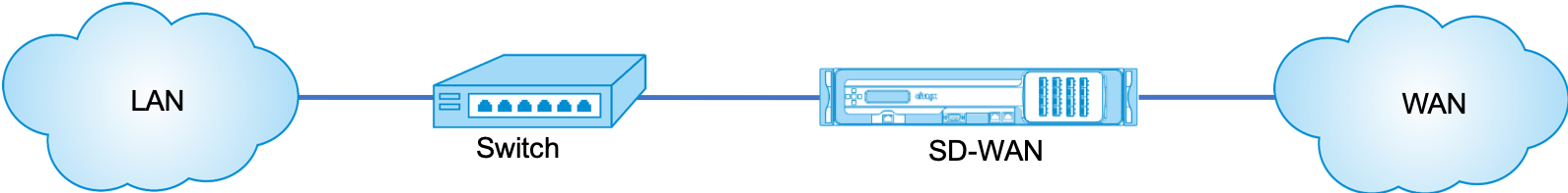
In the Inline mode, the SD-WAN appliance appears to be an Ethernet bridge. Most of the SD-WAN appliance models include a fail-to-wire (Ethernet bypass) feature for inline mode. If power fails, a relay closes and the input and output ports become electrically connected, allowing the Ethernet signal to pass through from one port to another. In the fail-to-wire mode, the SD-WAN appliance looks like a cross-over cable connecting the two ports. Inline mode used to integrate into already well-defined networks.
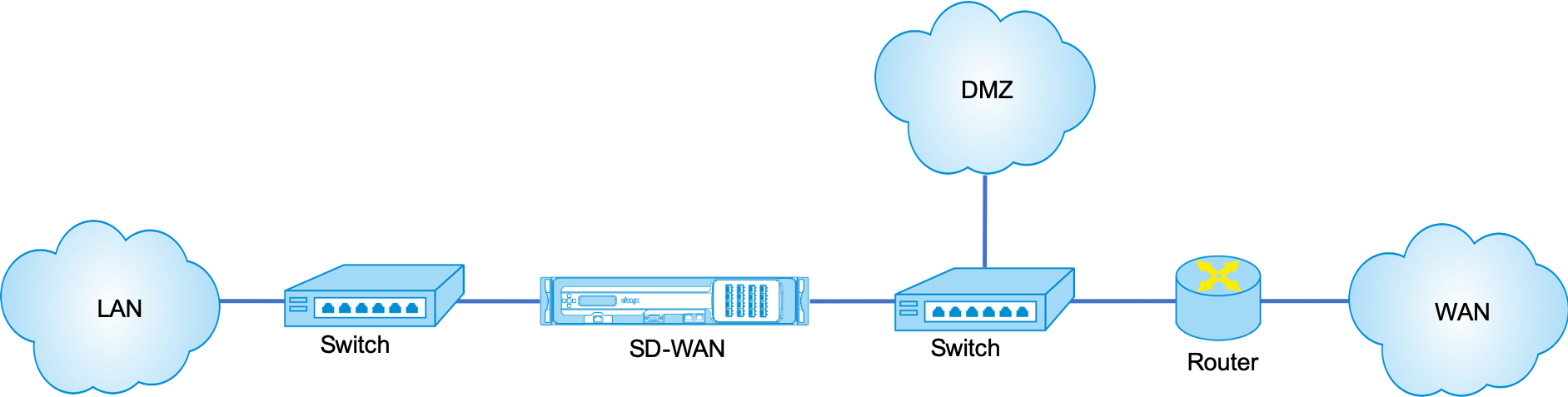
This article provides step-by-step procedure to configure an SD-WAN appliance in Gateway mode in a sample network setup. Inline deployment is also described for the branch side to complete the configuration. A network can continue to function if an Inline device is removed, but loses all access if the Gateway device is removed.
Topology
The following illustrations describe the topologies supported in an SD-WAN network.
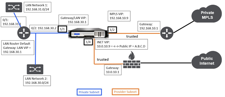
Data Center in gateway deployment
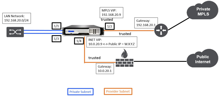
Branch in inline deployment
Deployment requirements
Deployment requirements and related information are described below to assist you in building the configuration.
| Site Name | Data center Site | Branch Site | |
|---|---|---|---|
| Appliance Name | A_DC1 | A_BR1 | |
| Management IP | 172.30.2.10/24 | 172.30.2.20/24 | |
| Security Key | If any | If any | |
| Model/Edition | 4000 | 2000 | |
| Mode | Gateway | Inline | |
| Topology | 2 x WAN Path | 2 x WAN Path | |
| VIP Address | 192.168.10.9/24 – MPLS, 10.0.10.9/24 – Internet (Public IP – A.B.C.D), 192.168.30.1/24 - LAN | 192.168.20.9/24 - MPLS, 10.0.20.9/24 – Internet (Public IP – W.X.Y.Z) | |
| Gateway MPLS | 192.168.10.1 | 192.168.20.1 | |
| Gateway Internet | 10.0.10.1 | 10.0.20.1 | |
| Link Speed | MPLS – 100 Mbps, | Internet – 20 Mbps | MPLS – 10 Mbps, Internet – 2 Mbps |
| Route | Network IP Address - 192.168.31.0/24, Service Type - Local, Gateway IP Address - 192.168.30.2 | If any | |
| VLANs | If any | If any |
Configuration pre-requisites
-
Enable SD-WAN appliance as a Master Control Node.
-
Configuration is done only on the Master Control Node (MCN) of the SD-WAN appliance.
To enable an appliance as a Master Control Node:
-
In the SD-WAN web management interface, navigate to Configuration > Appliance Settings > Administrator Interface > Miscellaneous tab > Switch Console.
Note
If “Switch to Client Console” is displayed, then the appliance is already in MCN mode. There should only be one active MCN in an SD-WAN network.
-
Start Configuration by navigating to Configuration > Virtual WAN > Configuration Editor. Click the New to begin configuration.
Data center site gateway mode configuration
Following are the high-level configuration steps to configure data center site Gateway deployment:
-
Create a DC site.
-
Populate Interface Groups based on connected Ethernet interfaces.
-
Create Virtual IP address for each virtual interface.
-
Populate WAN links based on physical rate and not burst speeds using Internet and MPLS Links.
-
Populate Routes if there are more subnets in the LAN infrastructure.
To create a DC site
-
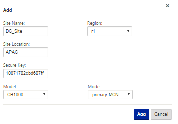
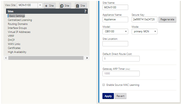
Navigate to Configuration Editor - > Sites, and click the ”+” Add button.
-
Populate the fields as shown below.
-
Keep default settings unless instructed to change.
To configure interface groups based on connected Ethernet interfaces
-
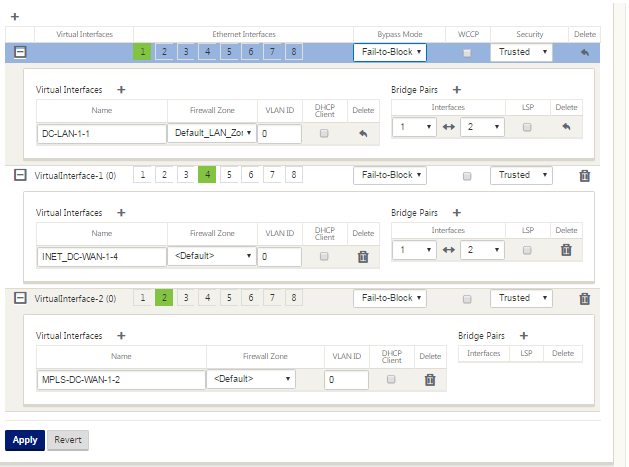
In the Configuration Editor, navigate to Sites > View Site > [Site Name] > Interface Groups. Click “+” to add interfaces intended to be used. For Gateway Mode, each Interface Group is assigned a single Ethernet interface.
-
Bypass mode is set to fail-to-block since only one Ethernet/physical interface is used per virtual interface. There are also no Bridge Pairs.
-
In this example three Interfaces Groups are created, one facing the LAN and two others facing each respective WAN Link. Refer to the sample “DC Gateway Mode” topology above and populate the Interface Groups fields as shown below.
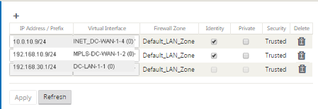
To create Virtual IP (VIP) address for each virtual interface
-
Create a VIP on the appropriate subnet for each WAN Link. VIPs are used for communication between two SD-WAN appliances in the Virtual WAN environment.
-
Create a Virtual IP Address to be used as the Gateway address for the LAN network.
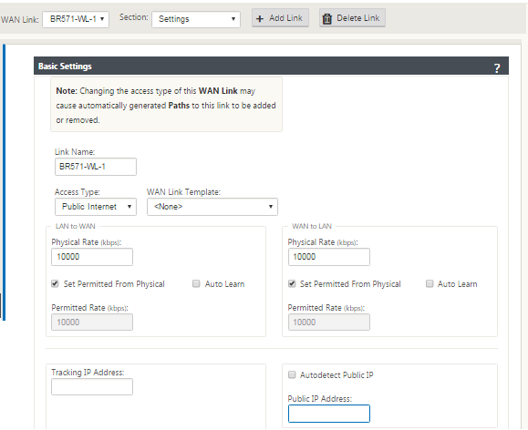
To populate WAN links based on physical rate and not on burst speeds using Internet link:
-
Navigate to WAN Links, click the “+ Add Link” button to add a WAN Link for the Internet link.
-
Populate Internet link details, including the supplied Public IP address as shown below. AutoDetect Public IP cannot be selected for SD-WAN appliance configured as MCN.
-
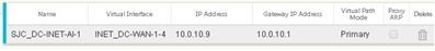
Navigate to Access Interfaces, from the section drop-down menu, and click the “+ Add” button to add interface details specific for the Internet link.
-
Populate Access Interface for IP and gateway addresses as shown below.
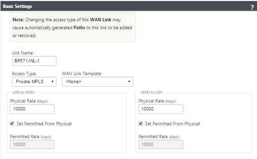
To create MPLS Link
-
Navigate to WAN Links, click the “+” button to add a WAN Link for the MPLS link.
-
Populate MPLS link details as shown below.
-
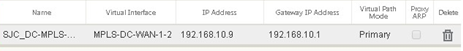
Navigate to Access Interfaces, click the “+” button to add interface detail specific for the MPLS link.
-
Populate Access Interface for IP and gateway addresses as shown below.
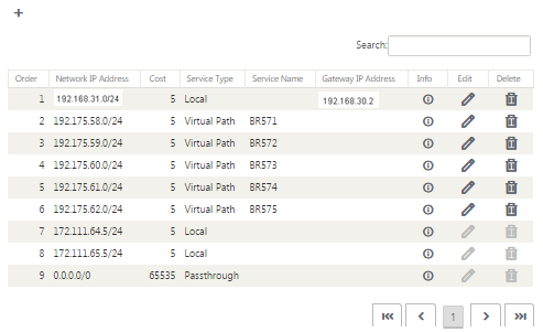
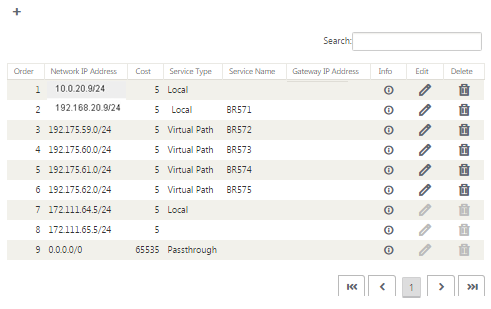
To populate Routes
Routes are auto-created based on the above configuration. The DC LAN sample topology shown above has an extra LAN subnet which is 192.168.31.0/24. A route needs to be created for this subnet. Gateway IP address must be in the same subnet as the DC LAN VIP as shown below.
Branch site inline deployment configuration
Following are the high-level configuration steps to configure Branch site for Inline deployment:
-
Create a Branch site.
-
Populate Interface Groups based on connected Ethernet interfaces.
-
Create Virtual IP address for each virtual interface.
-
Populate WAN links based on physical rate and not burst speeds using Internet and MPLS Links.
-
Populate Routes if there are more subnets in the LAN infrastructure.
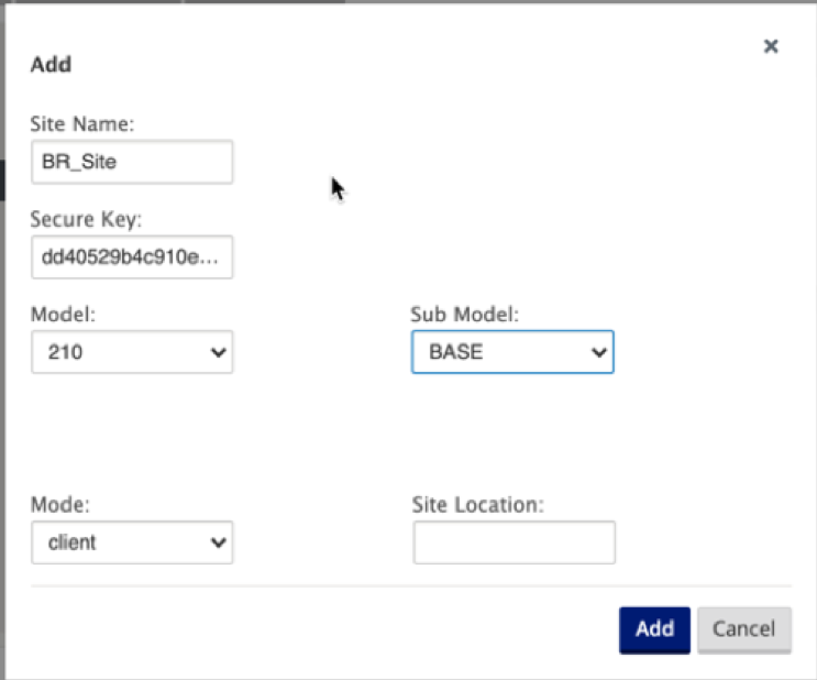
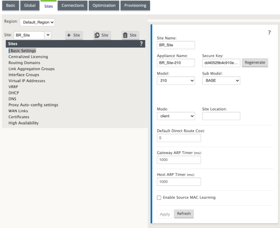
To create a Branch site
-
Navigate to Configuration Editor - > Sites, and click the “+” Add button.
-
Populate the fields as shown below.
-
Keep default settings unless instructed to change.
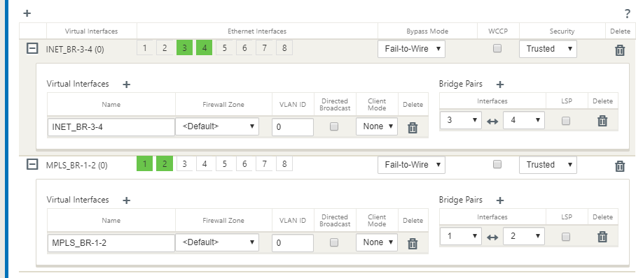
To populate interface groups based on connected Ethernet interfaces
-
In the Configuration Editor, navigate to Sites > View Site > [Client Site Name] > Interface Groups. Click + to add interfaces intended to be used. For Inline Mode, each Interface Group is assigned two Ethernet interfaces.
-
Bypass mode is set to fail-to-wire and Bridge Pair is created using the two Ethernet interfaces.
-
Refer to the sample “Remote Site Inline Mode” topology above and populate the Interface Groups fields as shown below.
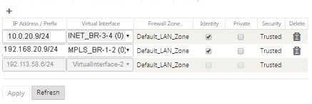
To create Virtual IP (VIP) address for each virtual interface
-
Create a Virtual IP address on the appropriate subnet for each WAN Link. VIPs are used for communication between two SD-WAN appliances in the Virtual WAN environment.
To populate WAN links based on physical rate and not on burst speeds using Internet link:
-
Navigate to WAN Links, click the “+” button to add a WAN Link for the Internet link.
-
Populate Internet link details, including the Auto Detect Public IP address as shown below.
-
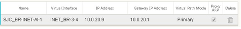
Navigate to Access Interfaces, click the “+” button to add interface details specific for the Internet link.
-
Populate Access Interface for IP address and gateway as shown below.
To create MPLS link
-
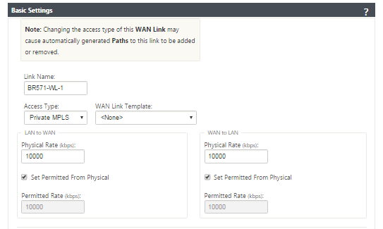
Navigate to WAN Links, click the “+” button to add a WAN Link for the MPLS link.
-
Populate MPLS link details as shown below.
-
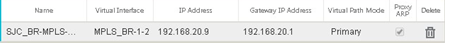
Navigate to Access Interfaces, click the “+” button to add interface details specific for the MPLS link.
-
Populate Access Interface for IP address and gateway as shown below.
To populate routes
Routes are auto-created based on above configuration. In case there are more subnets specific to this remote branch office, then specific routes need to be added identifying which gateway to direct traffic to reach those back-end subnets.
Resolve audit errors
After completing configuration for DC and Branch sites, you will be alerted to resolve audit error on both DC and BR sites.
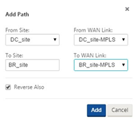
By default, the system generates paths for WAN Links defined as access type Public Internet. You would be required to use the auto-path group function or enable paths manually for WAN Links with an access type of Private Internet. Paths for MPLS links can be enabled by clicking Add operator (in the green rectangle).
After completing all the above steps, proceed to Preparing the SD-WAN Appliance Packages.
In this article
- Topology
- Data Center in gateway deployment
- Branch in inline deployment
- Deployment requirements
- Configuration pre-requisites
- Data center site gateway mode configuration
- To create a DC site
- To configure interface groups based on connected Ethernet interfaces
- To create Virtual IP (VIP) address for each virtual interface
- To create MPLS Link
- To populate Routes
- Branch site inline deployment configuration
- To create a Branch site
- To populate interface groups based on connected Ethernet interfaces
- To create Virtual IP (VIP) address for each virtual interface
- To create MPLS link
- To populate routes
- Resolve audit errors