Virtual inline mode
In virtual inline mode, the router uses routing protocol such as PBR, OSPF, or BGP to redirect incoming and outgoing WAN traffic to the appliance, and the appliance forwards the processed packets back to the router.
The following article describes the step-by-step procedure to configure two SD-WAN (SD-WAN SE) appliances:
- Data Center appliance in virtual inline mode
- Branch appliance in Inline mode
- Routing protocol must be configured either at the core switch or further upstream at the router. The router must monitor the health of the SD-WAN appliance so that the appliance can be bypassed if it fails.
- Virtual inline mode places the SD-WAN appliance physically out of path (one-arm deployment) that is, only a single Ethernet interface to be used (Example: Interface 1/5) with bypass mode set to fail-to-block (FTB). Citrix SD-WAN appliance must be configured to pass traffic to the proper gateway. Traffic intended for the Virtual Path is directed towards the SD-WAN appliance and then encapsulated and directed to the appropriate WAN link.
Gather information
Gather the following information required for configuring virtual inline mode:
- Accurate network diagram of your local and remote sites including:
- Local and Remote WAN links and their bandwidths in both directions, their subnets, Virtual IP Addresses and Gateways from each link, Routes, and VLANs.
- Deployment Table
The following is a sample network diagram and deployment table:
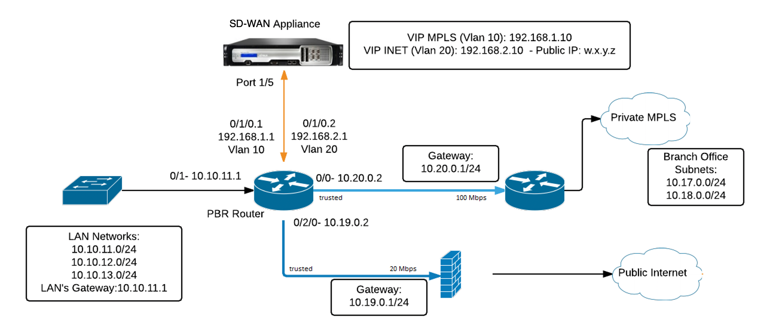
Data center topology – Virtual inline mode
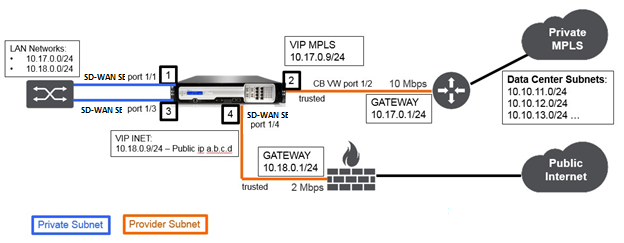
Branch topology – inline mode
| Site Name | Data center Site | Branch Site |
|---|---|---|
| Appliance Name | SJC-DC | SJC-BR |
| Management IP | 172.30.2.10/24 | 172.30.2.20/24 |
| Security Key | If any | If any |
| Model/Edition | 4000 | 2000 |
| Mode | Virtual Inline Mode | Inline |
| Topology | 2 x WAN Path | 2 x WAN Path |
| VIP Address | 192.168.1.10/24 – MPLS, 192.168.2.10/24 – Internet, Public IP w.x.y.z | 10.17.0.9/24 - MPLS, 10.18.0.9/24 – Internet, Public IP a.b.c.d |
| Gateway MPLS | 10.20.0.1 | 10.17.0.1 |
| Gateway Internet | 10.19.0.1 | 10.18.0.1 |
| Link Speed | MPLS – 100 Mbps, Internet – 20 Mbps | MPLS – 10 Mbps, Internet – 2 Mbps |
| Route | Need to add a route on the SD-WAN SE Appliance on how to reach the LAN Subnets (10.10.11.0/24, 10.10.12.0/24, 10.10.13.0/24, and so on) through any of the physical interfaces: Gi0/1 - 192.168.1.1, Configuration > Virtual WAN > Configuration Editor > SJC_DC \ > Routes. In this example interface 192.168.1.1 was used: - n/w address: 10.10.13.0/24, 10.10.12.0/24, 10.10.11.0/24, - Service type: local, - Gateway IP address: 192.168.1.1 | No additional routes were added |
| VLANs | MPLS - VLAN 10, Internet - VLAN 20 | None (default 0) |
Prerequisites
-
In the SD-WAN appliance web management interface, navigate to Configuration > Appliance Settings > Administrator Interface > Miscellaneous tab and click Switch Console.
Note
If Switch to Client Console is displayed, then the appliance is already in MCN mode. You must have only one active MCN in an SD-WAN network.
-
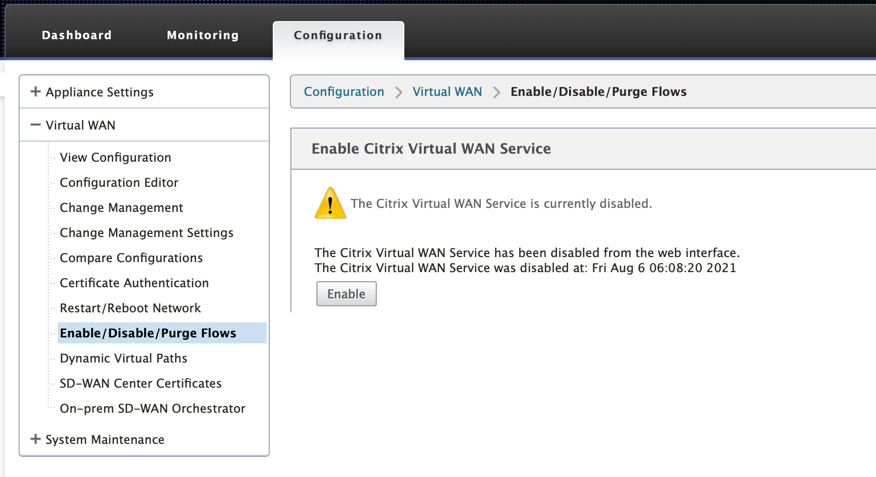
Navigate to Configuration > Virtual WAN > Enable/Disable/Purge Flows and click Enable in the Enable Citrix Virtual WAN Service section.
-
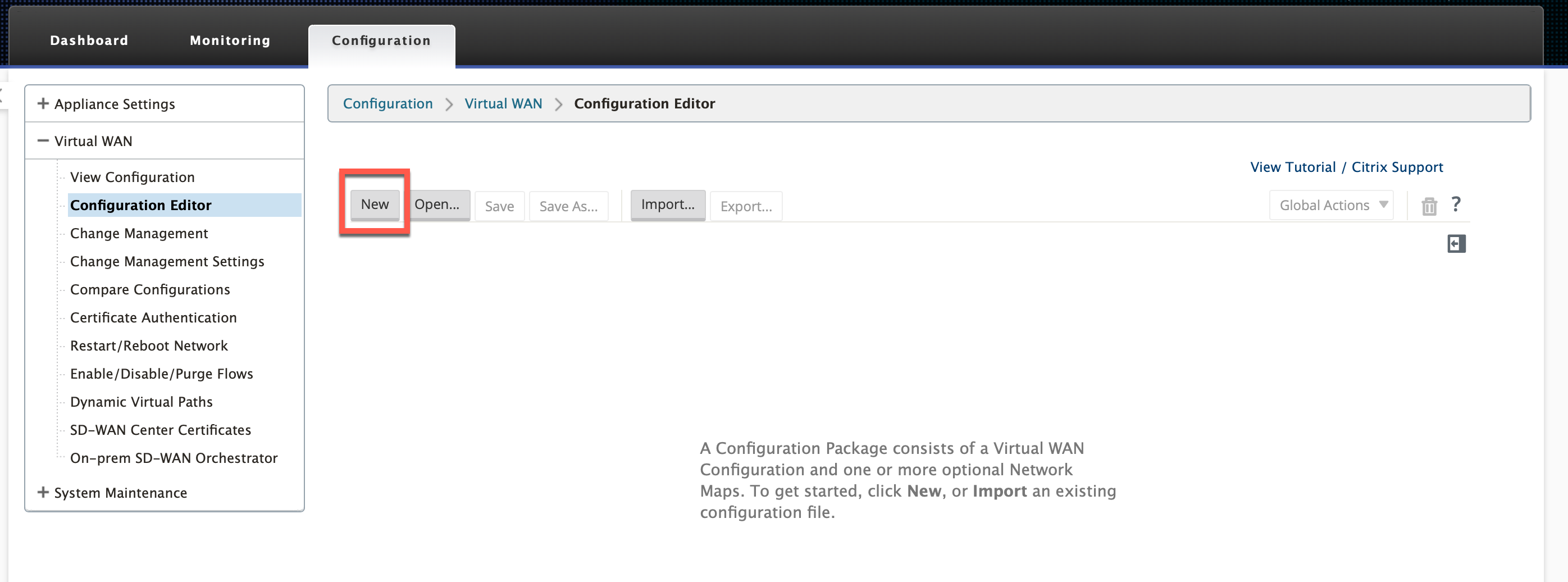
Start Configuration by navigating to Configuration > Virtual WAN > Configuration Editor. Click New to begin the configuration. Clicking New creates an initial configuration file having Untitled_1 as the file name. You can rename [optional] the file later using the Save As button.
Data center site - virtual inline mode configuration
Create a data center site
-
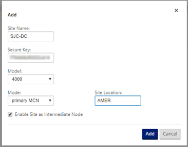
Navigate to Configuration > Virtual WAN > Configuration Editor > Sites and click + Site.
-
Enter the site name and location. Choose the appliance model from the Model drop-down list and Primary MCN from the Mode drop-down list.
-
Click Add.
Configure interface groups based on connected Ethernet interfaces
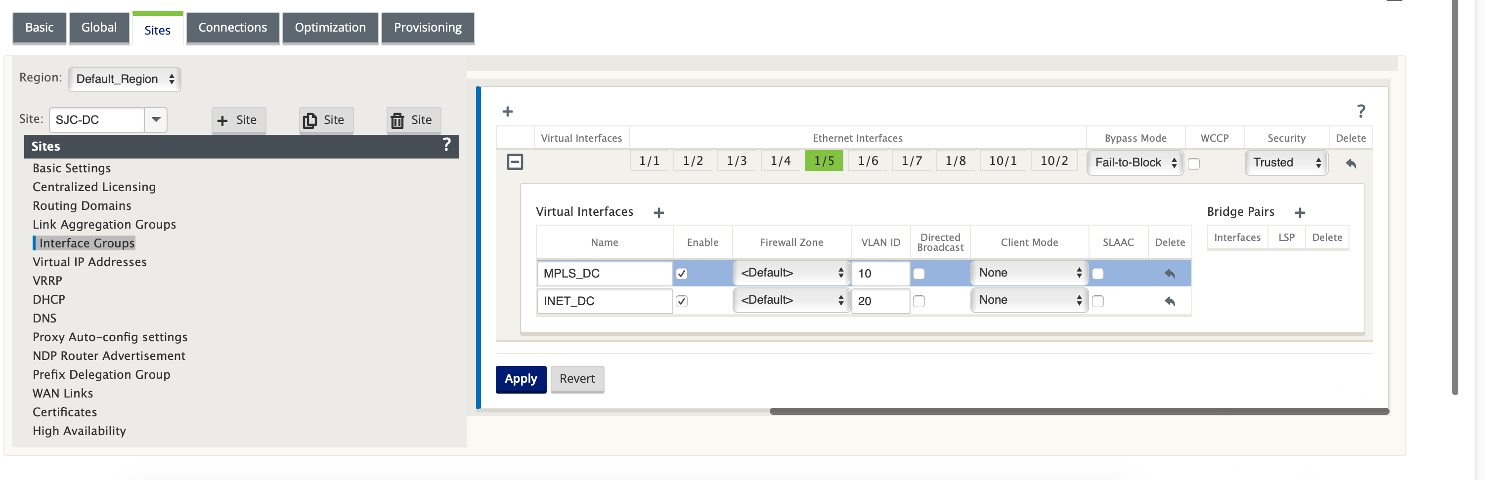
In virtual inline mode configuration, only one Ethernet interface is used, that is, the interface connecting the upstream router providing routing policy implications (Example-Interface 1/5). Bypass mode is set to Fail-to-Block (FTB) since only one Ethernet/physical interface is used per virtual interface. Also, there are no Bridge Pairs.
-
In the Configuration Editor, navigate to Sites > [Site Name] > Interface Groups. Click + to add interfaces intended to be used.
- Select the Ethernet interface that gets connected to the upstream router and click + next to Virtual Interfaces. Add the Virtual Interfaces for both MPLS and INTERNET links. As per the sample topology, add the following:
- Virtual Interface MPLS configured on VLAN 10
- Virtual Interface INTERNET configured on VLAN 20
-
Select Fail-to-Block from the Bypass Mode drop-down list. Click Apply.
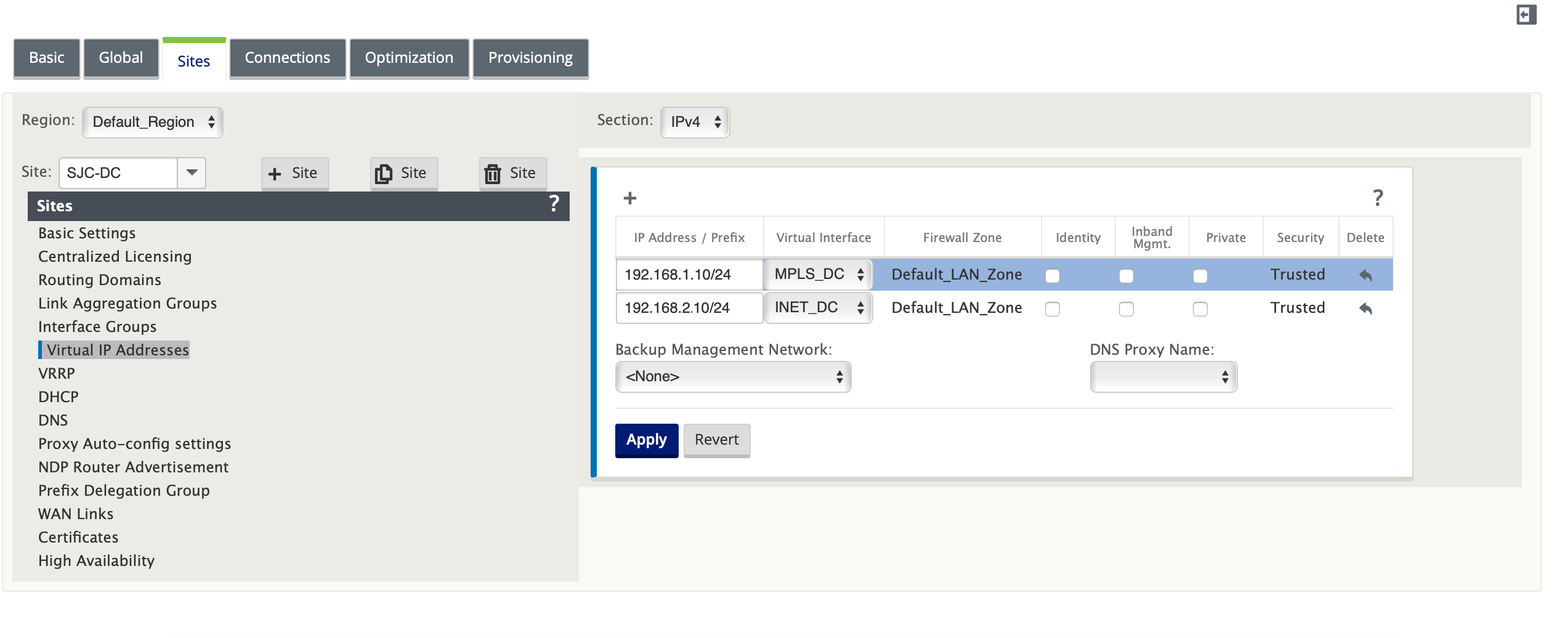
Create Virtual IP address for each virtual interface
Create a Virtual IP (VIP) Address on the appropriate subnet for each WAN Link. VIPs are used for communication between two SD-WAN appliances in the Virtual WAN environment.
-
In the Configuration Editor, navigate to Sites > [Site Name] > Virtual IP Addresses. Click + to create VIPs.
-
Enter the IP address/prefix and select the corresponding virtual interface for MPLS and Internet.
-
Click Apply.
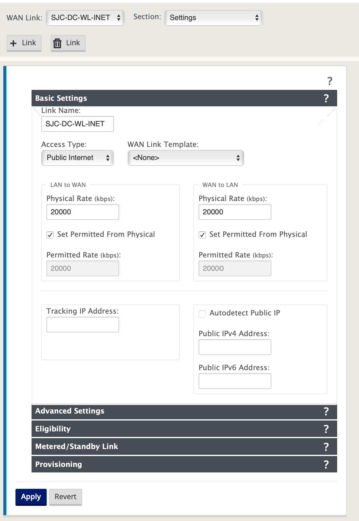
Create Internet WAN link
Create Internet WAN link based on physical rate and not on burst speeds.
-
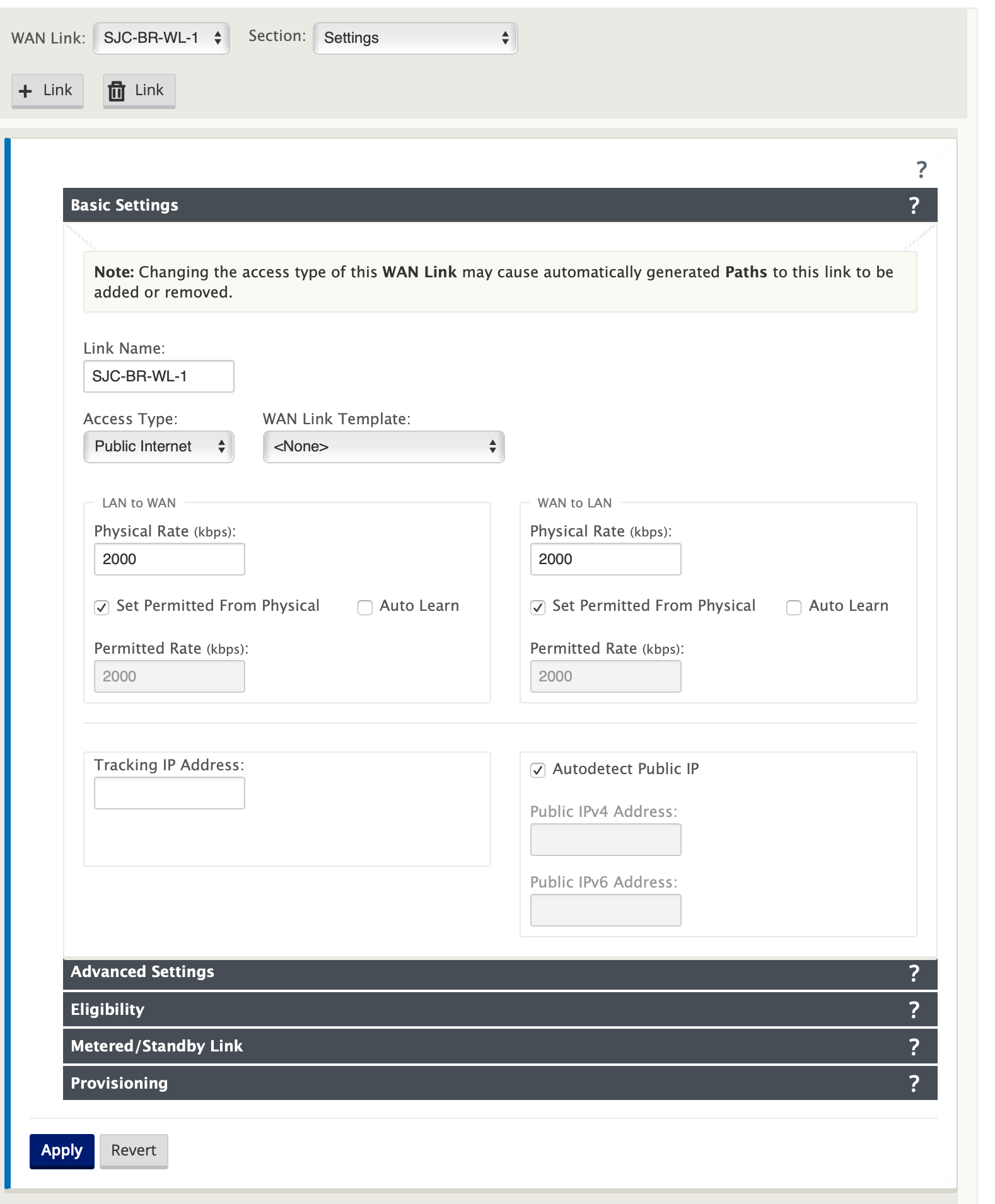
In the Configuration Editor, navigate to Sites > [Site Name] > WAN Links and click + Link. Enter a name and select Access Type as Public Internet. Click Add.
-
Enter the physical rate. Do not select the Auto Detect Public IP check box. For the SD-WAN appliance that is configured as MCN, the Auto Detect Public IP check box cannot be selected.
-
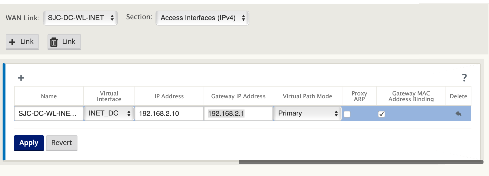
Select Access Interfaces from the Section drop-down list and click the + button to add interface details specific for the Internet link.
-
Enter the Internet WAN virtual IP address and gateway address. The Proxy ARP is not checked for less than two Ethernet interfaces.
-
Click Apply.
Create MPLS link
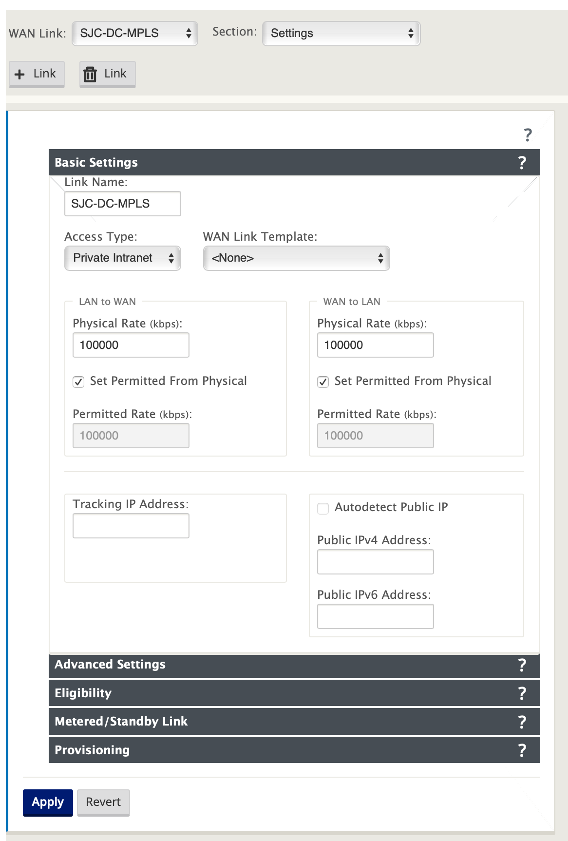
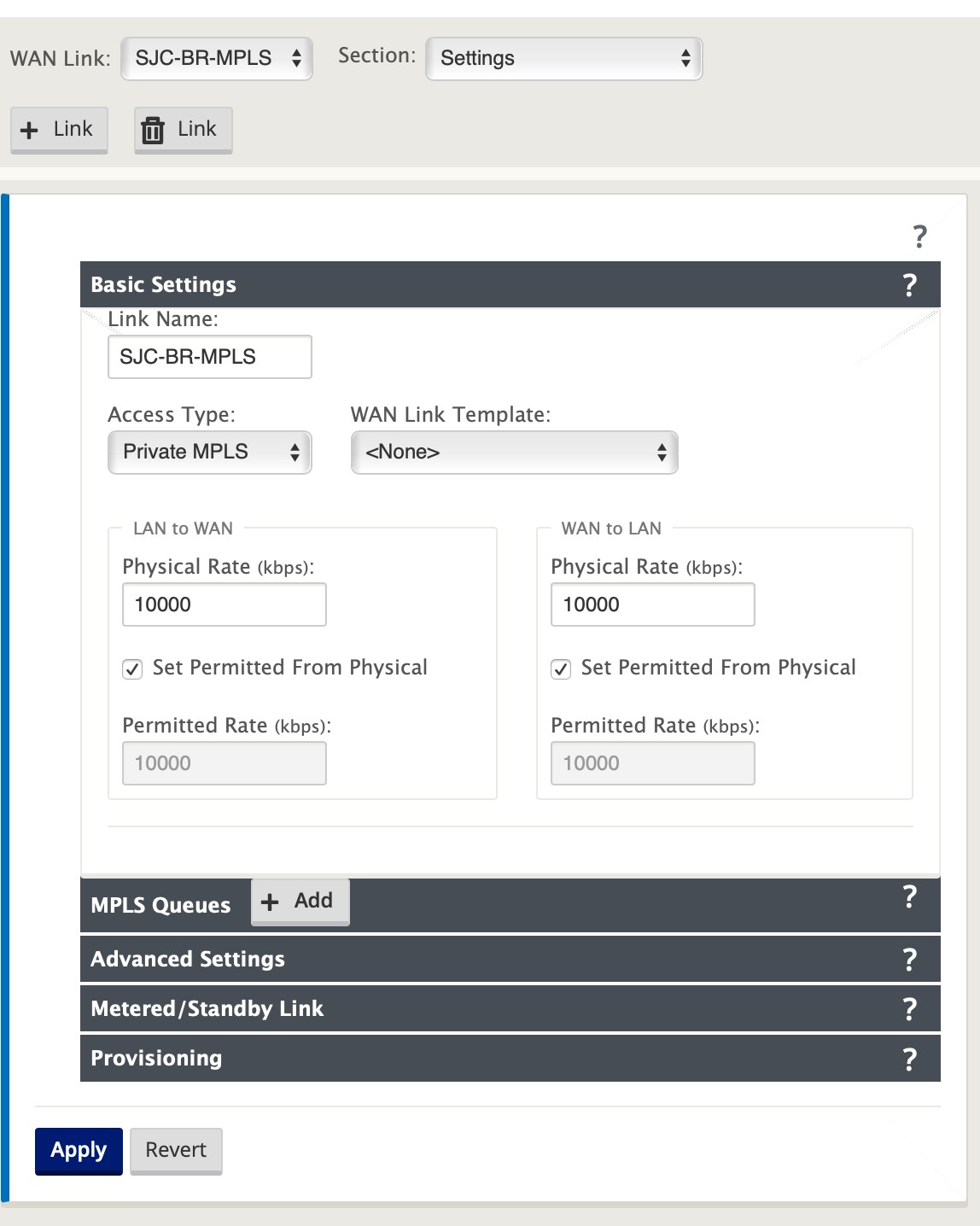
- In the Sites > [Site Name] > WAN Links page, select Settings from the Section drop-down list. Click the + Link button to add a WAN Link for MPLS.
-
Enter the MPLS WAN Link name and select Access Type as Private Intranet. Click Add.
-
Enter the physical rate and other details. Click Apply.
-
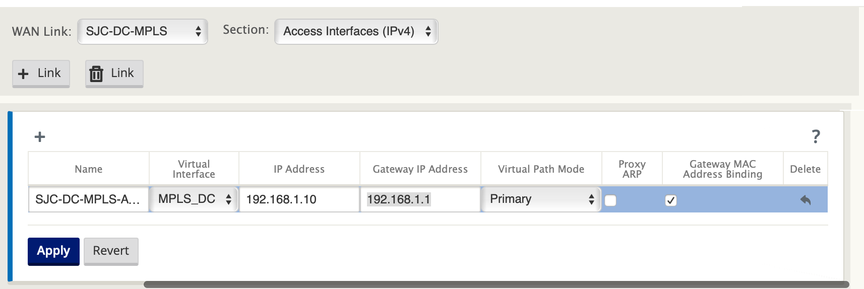
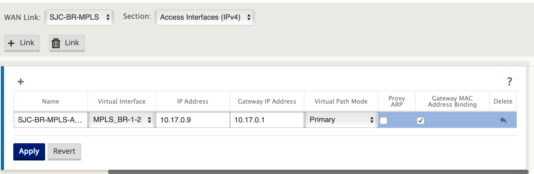
Select Access Interfaces from the Section drop-down list and click the + button to add interface details specific to the MPLS link.
-
Enter the MPLS Virtual IP address and Gateway address. The Proxy ARP is not checked for less than two Ethernet interfaces.
-
Click Apply.
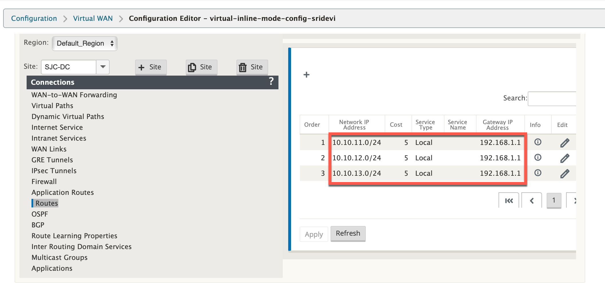
Populate routes
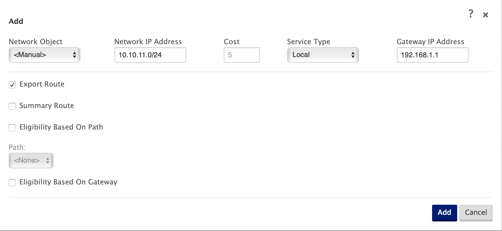
On the data center side, add a route on the SD-WAN appliance on how to reach the LAN Subnets (10.10.11.0/24, 10.10.12.0/24, 10.10.13.0/24, and so on) through any of the physical interfaces.
0/1/0.1 – 192.168.1.1 on VLAN 10
0/1/0.2 – 192.168.2.1 on VLAN 20
In this example, the interface 192.168.1.1 is used.
In the Configuration Editor, navigate to Connections > Routes and click + to add the routes.
Enter the Network IP address, Cost, and Gateway address. Click Add.
Branch site inline deployment configuration
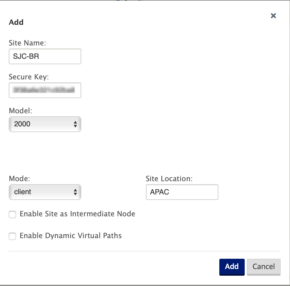
Create a branch site
-
Navigate to Configuration Editor > Sites and click + Site.
-
Enter the site name and location. Choose the appliance model from the Model drop-down list and Client from the Mode drop-down list.
-
Click Add.
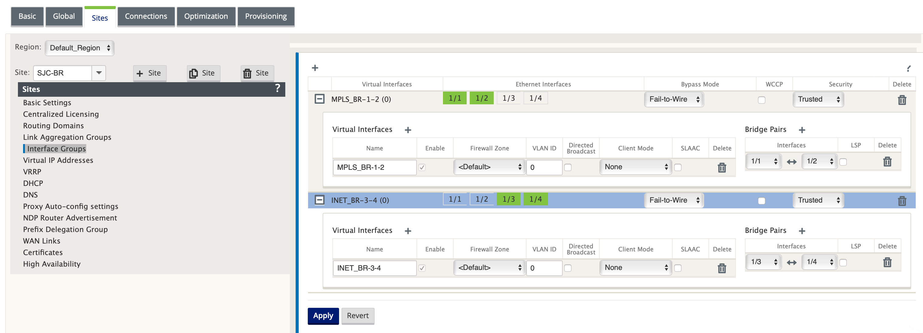
Configure interface groups based on connected Ethernet interfaces
-
In the Configuration Editor, navigate to Sites > [Client Site Name] > Interface Groups. Click + to add interfaces intended to be used. For Inline mode configuration, four Ethernet interfaces are used; interface pair 1/3, 1/4 and interface pair 1/1 and 1/2.
-
Set the Bypass mode to fail-to-wire since two Ethernet/physical interfaces are used per virtual interface. There are two bridge Pairs.
-
Click + next to Virtual Interfaces and populate WAN links based on physical rate and not burst speeds using Internet and MPLS Links.
-
Virtual Interface INTERNET configured on Bridge pair 1/3 and 1/4
-
Virtual Interface MPLS configured on Bridge Pair 1/1 and 1/2.
-
-
Click + next to Bridge Pairs and create the bridge pair by selecting the appropriate interfaces.
Refer to the Branch topology – inline mode topology diagram under the Prerequisites section and populate the Interface Groups.
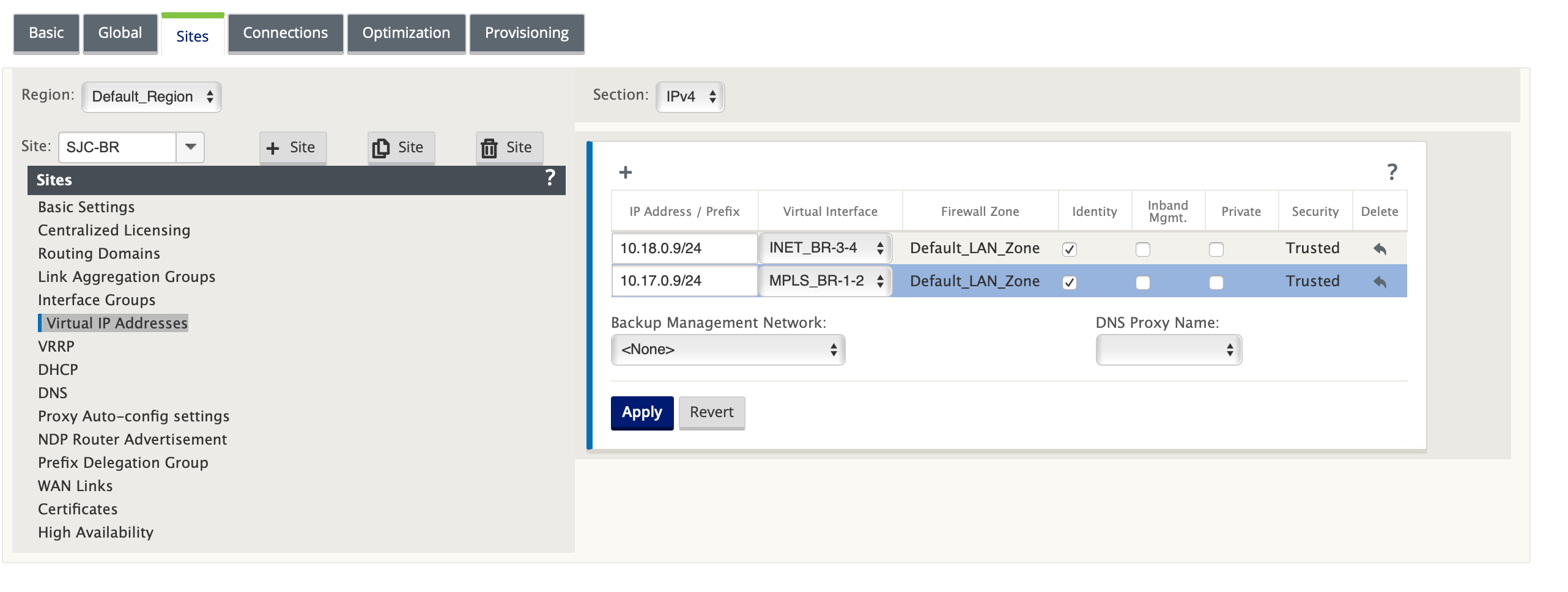
Create Virtual IP (VIP) address for each virtual interface
Create a Virtual IP address on the appropriate subnet for each WAN Link. VIPs are used for communication between two SD-WAN appliances in the Virtual WAN environment.
-
In the Configuration Editor, navigate to Sites > [Site Name] > Virtual IP Addresses. Click + to create VIPs.
-
Enter the IP address/prefix and select the corresponding virtual interface for MPLS and Internet.
-
Click Apply.
Create Internet WAN link
To populate WAN links based on physical rate and not on burst speeds using Internet link
-
Navigate to WAN Links, click the + Link button to add a WAN Link for the Internet link. Enter a name and select Access Type as Public Internet. Click Add.
-
Populate Internet link details and select the Autodetect Public IP address check box.
-
Select Access Interfaces from the Section drop-down list and click the + to add interface details specific for the Internet link.
-
Enter the Internet WAN virtual IP address and gateway address. The Proxy ARP is not checked for less than two Ethernet interfaces.
Create MPLS WAN link
-
Navigate to WAN Links and select Settings from the Section drop-down list. Click the + Link button to add a WAN Link for the MPLS link.
-
Enter the MPLS WAN Link name and other details. Select Access Type as Private Intranet.
-
Select Access Interfaces from the Section drop-down list and click the + button to add interface details specific for the MPLS link.
-
Enter the MPLS Virtual IP address and Gateway address. The Proxy ARP is not checked for less than two Ethernet interfaces.
Populate routes
Routes are auto-created based on preceding configuration. If there are more subnets specific to this remote branch office, then specific routes need to be added identifying which gateway to direct traffic to reach those back-end subnets.
Create Autopath groups
-
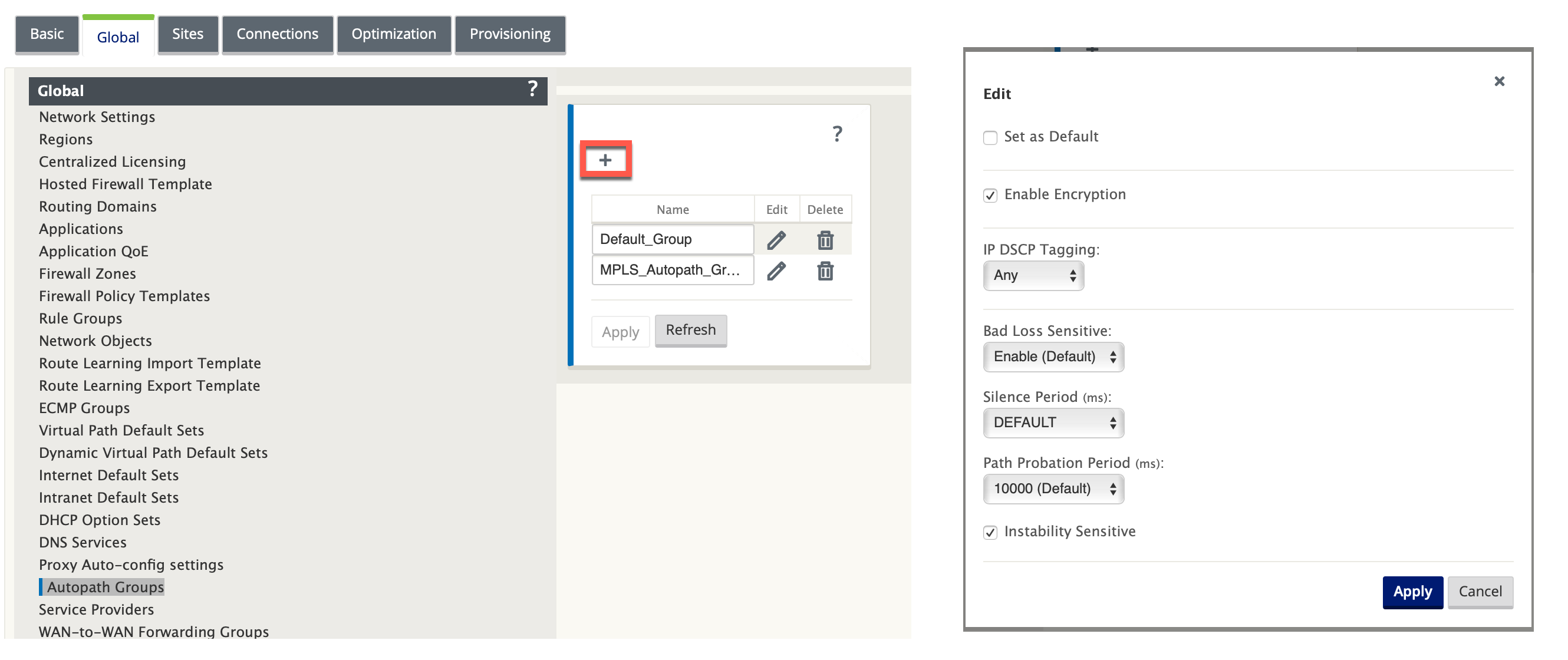
In the Configuration Editor, navigate to the Global > Autopath Groups. Click +.
-
Enter a name and click Apply.
-
Configure the Autopath Group as per your requirement and click Apply.
-
Navigate to Connections > WAN links. Select the Internet WAN link from the WAN Links drop-down list and Virtual Paths from the Section drop-down list.
-
Select the Use check box and choose the newly created autopath group from the Autopath Group check box for the Intranet WAN links at the respective sites (both Data Center and Branch).
No two Autopath Groups can be marked as default. If marked would lead to an audit error.
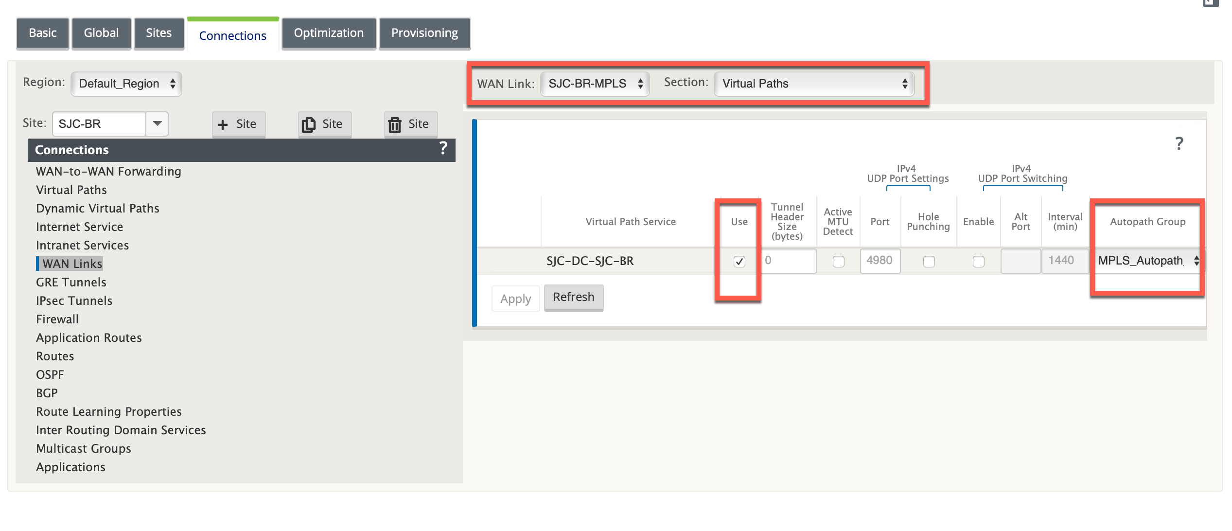
After manually adding the virtual paths for WAN links with access type as Private Intranet, virtual paths get populated under Paths.
After completing all the preceding steps, proceed to Preparing the SD-WAN Appliance Packages.
Resolving audit errors
After completing the configuration for Data Center and Branch sites, you will be alerted to resolve the audit errors on both DC and BR sites. Resolve the audit errors (if any).