Configure MCN
The first step is to open a new configuration package, and add the MCN site to the new configuration.
Note
The Configuration Editor is available in MCN Console mode, only. If the Configuration Editor option is not available in the Virtual WAN branch of the navigation tree, see section, Switching the Management Web Interface to MCN Console Mode, for instructions on changing the console mode.
It is recommended that you save the configuration package often, or at key points in the configuration. Instructions are provided in the section Naming, Saving, and Backing Up the MCN Site Configuration.
Warning
If the console session times out or you log out of the Management Web Interface before saving your configuration, any unsaved configuration changes are lost. You must then log back into the system, and repeat the configuration procedure from the beginning. For that reason, it is recommended that you set the console session Timeout interval to a high value when creating or modifying a configuration package, or performing other complex tasks. The default is 60 minutes. The maximum is 9,999 minutes. For security reasons, you must then reset it to a lower threshold after completing those tasks. For instructions, see the section Setting the Console Session Timeout Interval (Optional)
To add and begin configuring the MCN appliance site, do the following:
-
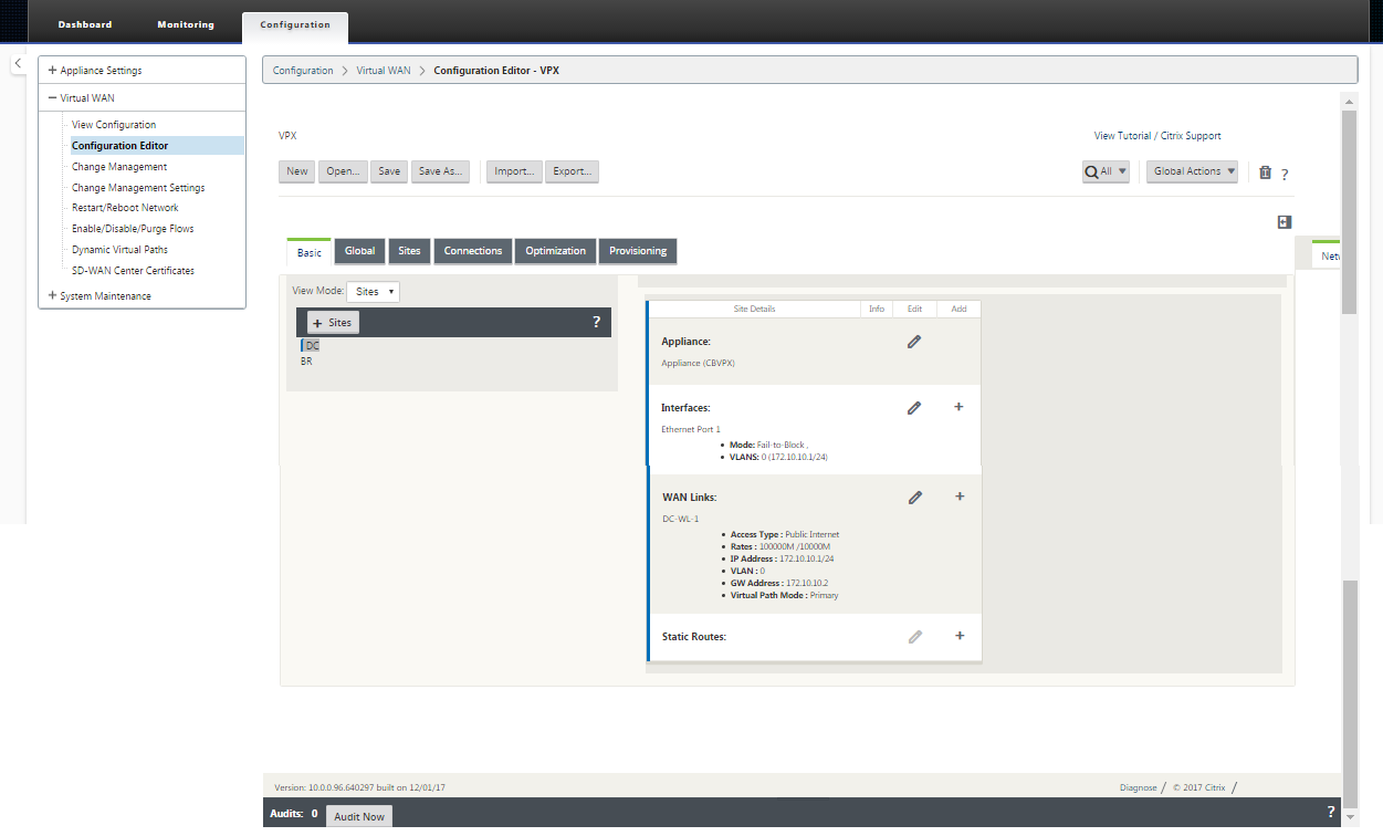
In the navigation tree, navigate to Virtual WAN > Configuration Editor. This displays the Configuration Editor main page (middle pane).
-
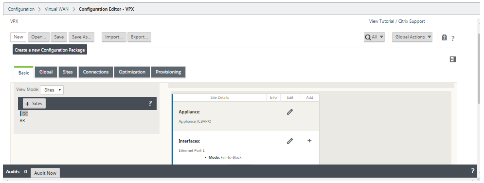
Click New to start defining a new configuration. This displays the New configuration settings page.
-
Click + Sites in the Sites bar to begin adding and configuring the MCN site. This displays the Add Site dialog box.
-
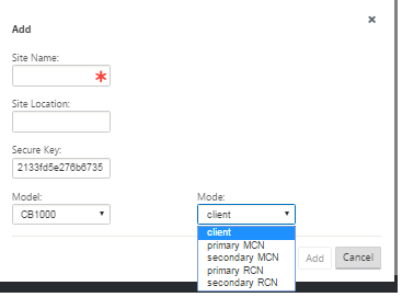
Enter the site information.
Do the following:
- Enter the Site Name and Secure Key.
- Select the appliance Model.
- Select the Mode.
- Select primary MCN as the mode.
Note
The Model options menu lists the generic model names for the supported appliance models. The generic names do not include the Standard Edition model suffix, but do correspond to the equivalent SD-WAN Appliance models. Select the corresponding model number for this SD-WAN Appliance model. (For example, select 4000 if this is an SD-WAN 4000-SE appliance.)
Entries cannot contain spaces and must be in Linux format.
To add site:
-
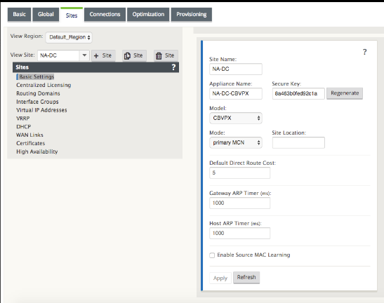
Click Add to add the site. This adds the new site to the Sites tree, and displays the Basic Settings configuration form for the new site.
After you click Apply, audit warnings appear indicating that further action is required. A red dot or goldenrod delta icon indicates an error in the section where it appears. You can use these warnings to identify errors or missing configuration information. Roll your cursor over an audit warning icon to display a short description of the errors in that section. You can also click the dark gray Audits status bar (bottom of page) to display a complete list of all unresolved audit warnings. Configurable Host ARP Timer (ms) is added at a Site level during configuration. The current default value is 1,000 ms. The configurable range is from 1,000 ms through 180,000 ms. The Host ARP timer configuration is not applicable to management port.
-
Enter the basic settings for the new site, or accept the defaults. In Citrix SD-WAN deployments such as Gateway and One-arm, when the ARP requests are received frequently, the access points become overloaded affecting traffic flow. You can now configure ARP timers to send the ARP requests with specific interval times. The time interval is configured in seconds. You can configure ARP time intervals when configuring the data center site under Basic Settings tab in the Citrix SD-WAN appliance GUI.
-
(Optional, recommended) Save the configuration-in-progress.
If you cannot complete the configuration in one session, you can save it at any time, so you can return to complete it later. The configuration is saved to your workspace on the local appliance. To resume working in a saved configuration, click Open in the Configuration Editor menu bar (top of page area). This displays a dialog box for selecting the configuration you want to modify.
Note
As an extra precaution, it is recommended that you use Save As, rather than Save, to avoid overwriting the wrong configuration package.
To save the current configuration package, do the following:
-
Click Save As (at the top of the Configuration Editor middle pane). This opens the Save As dialog box.
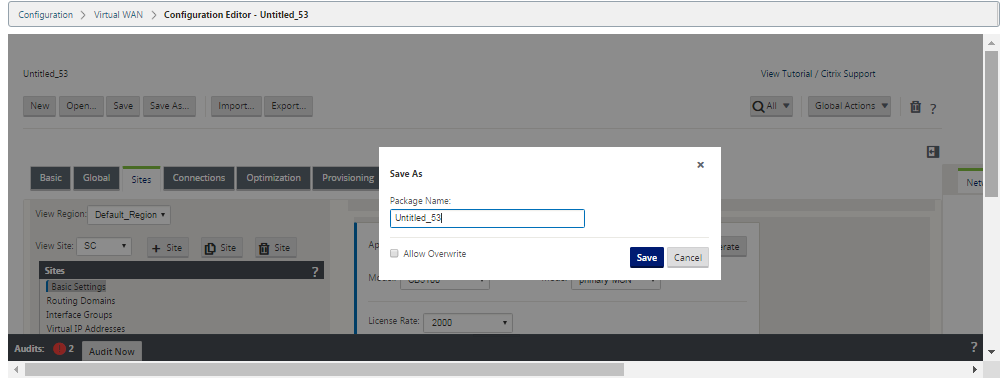
-
Enter the configuration package name. If you are saving the configuration to an existing package, be sure to select Allow Overwrite before saving.
-
Click Save.
How to configure interface groups for the MCN
After adding the new MCN site, the next step is to create and configure the Virtual Interface Groups for the site.
The following are some guidelines for configuring Virtual Interface groups:
-
Use logical names that will best describe the group.
-
Trusted networks are networks that are protected behind a Firewall.
-
Virtual Interfaces associate interfaces to Fail to Wire (FTW) pairs.
-
Single WAN interfaces cannot be in an FTW pair.
-
IPv6 address is introduced in 11.1.0 release and it is only supported for untrusted interfaces. Untrusted interfaces are non-routable and used for virtual path traffic.
Note
For more guidelines and information on configuring Virtual Interface Groups, see the Virtual Routing and Forwarding section.
To add a Virtual Interface Group to the new MCN site, do the following:
-
Continuing in the Sites view of the Configuration Editor, select the site from the View Site drop-down menu. This opens the configuration view for the site you selected.
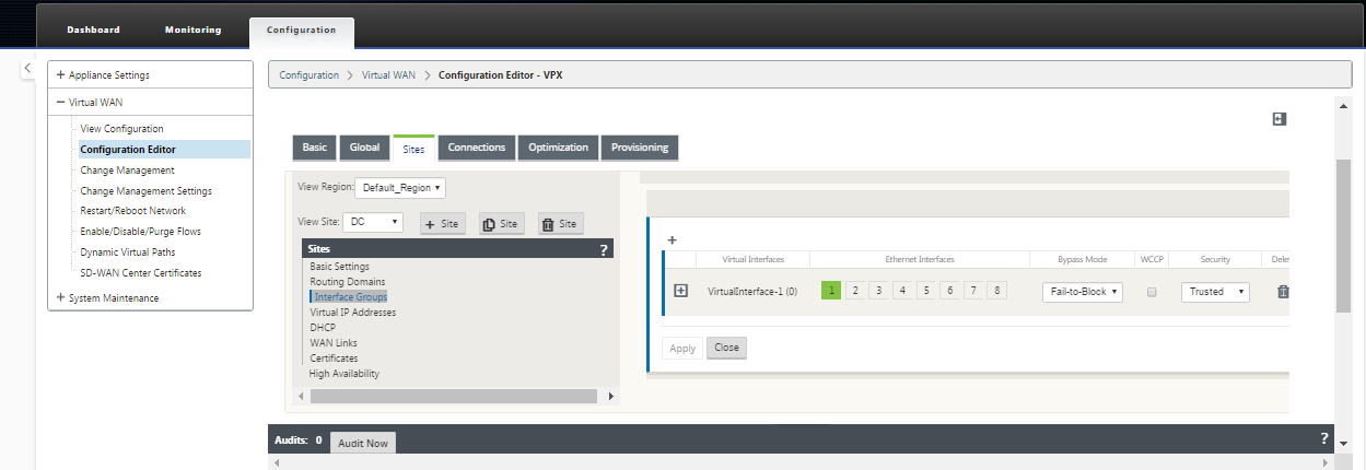
-
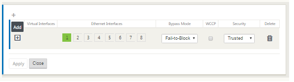
Click + to add the Virtual Interface Group. This adds a new blank Virtual interface group entry to the table and opens it for editing.
-
Click + to the right of Virtual Interfaces. This adds a new blank group entry to the table and opens it for editing.
-
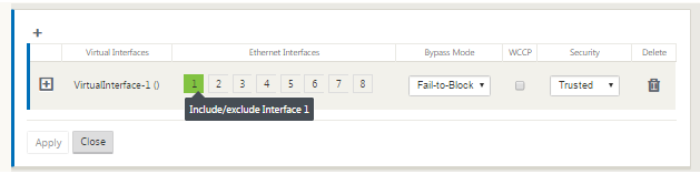
Select the Ethernet Interfaces to include in the group. Under Ethernet Interfaces, click an interface to include/exclude that interface. You can select any number of interfaces to include in the group.
-
Select the Bypass Mode from the drop-down menu (no default). The Bypass Mode specifies the behavior of bridge-paired interfaces in the Virtual Interface Group, in the event of an appliance or service failure or restart. The options are: Fail-to-Wire or Fail-to-Block.
-
Select the Security Level from the drop-down menu. This specifies the security level for the network segment of the Virtual Interface Group. The options are: Trusted or Untrusted. Trusted segments are protected by a firewall (default is Trusted).
-
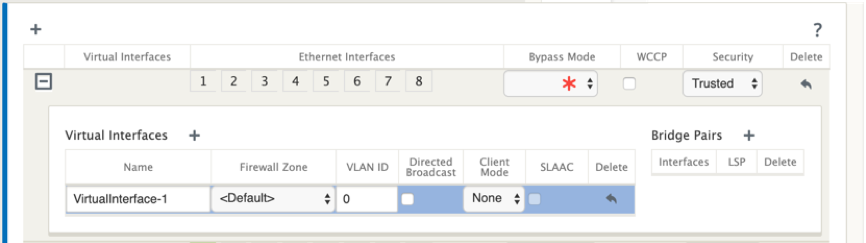
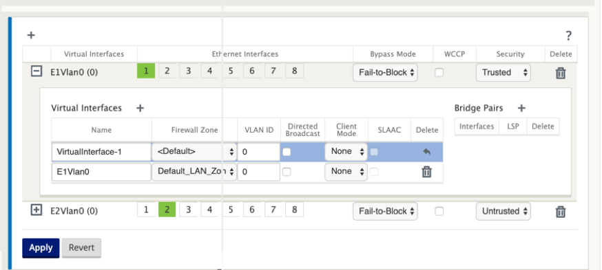
Click + at the left edge of the Virtual Interface you added. This displays the Virtual Interfaces table.
-
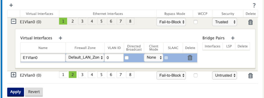
Click + to the right of Virtual Interfaces. This reveals the Name, Firewall Zone, VLAN ID, Directed Broadcast, Client Mode, and Stateless Address Auto-Configuration (SLAAC).
-
Enter the Name and VLAN ID for this Virtual Interface Group.
- Name – This is the name by which this Virtual Interface is referenced.
- Firewall Zone - Select a firewall zone from the drop-down menu.
- VLAN ID – This is the ID for identifying and marking traffic to and from the Virtual Interface. Use an ID of 0 (zero) for native/untagged traffic.
- Client Mode – Select the client mode from the drop-down menu.
- Directed Broadcast - On the virtual interface, Directed Broadcasts packets can be forwarded for Virtual IP subnets by enabling the check box.
-
SLAAC – Enabling Stateless Address Auto-Configuration (SLAAC) check box on a Virtual Interface allows it to automatically obtain a global IPv6 address from the connected router. Virtual Interfaces with SLAAC turned on do not require a configured Virtual IP Address.
NOTE SLAAC can only be enabled on a branch site on an untrusted interface.
You have the ability to release or renew the IP addresses for SLAAC.
-
Click + to the right of Bridge Pairs. This adds a new Bridge Pairs entry and opens it for editing.
-
Select the Ethernet interfaces to be paired from the drop-down menus. To add more pairs, click + next to Bridge Pairs again.
-
Click Apply. This applies your settings and adds the new Virtual Interface Group to the table. At this stage, you see a yellow delta Audit Alert icon, to the right of the new Virtual Interface Group entry. This is because you have not yet configured any Virtual IP Addresses (VIPs) for the site. For now, you can ignore this alert, as it is resolved automatically when you have properly configured the Virtual IPs for the site.
-
To add more Virtual Interface Groups, click + to the right of the Interface Groups branch, and proceed as shown above.
How to configure virtual IP address for the MCN
The next step is to configure the Virtual IP Addresses for the site, and assign them to the appropriate group.
-
Continuing in the Sites view for the new MCN site, click + to the left of the Virtual IP Addresses. This displays the Virtual IP Addresses table for the new site.
-
Click + to the right of Virtual IP Addresses to add an address. This opens the form for adding and configuring a new Virtual IP Address.
-
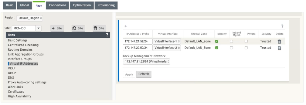
Enter the IP Address / Prefix information, and select the Virtual Interface with which the address is associated. The Virtual IP Address must include the full host address and netmask.
-
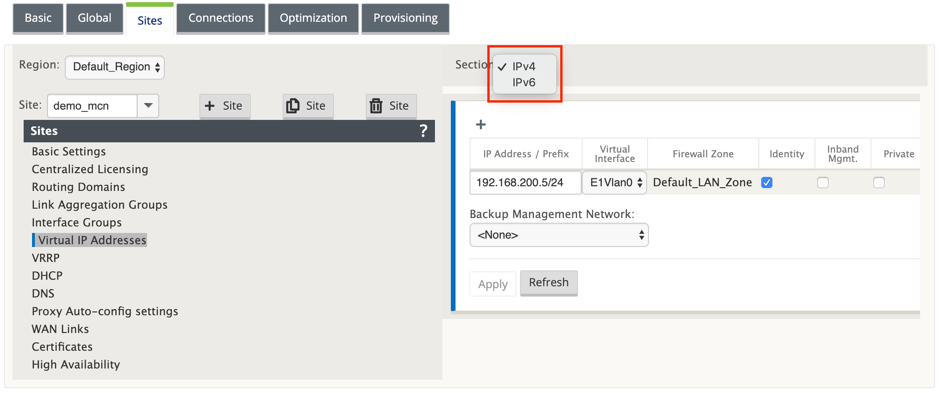
Select the desired settings for the Virtual IP address; such as the Firewall Zone, Identity, Private, and Security.
-
Select Inband Mgmt to allow the virtual IP address to connect to management services such as web UI and SSH.
Note:
The interface should be of security type Trusted and Identity enabled.
-
Select a virtual IP as a Backup Management Network. This allows you to use the virtual IP address for management if the management port is not configured with a default gateway.
-
Click Apply. This adds the address information to the site and includes it in the site Virtual IP Addresses table.
-
To add more Virtual IP Addresses, click + to the right of the Virtual IP Addresses, and proceed as above.
From 11.1.0 release onwards, there are two subsections available under the Virtual IP Address : IPv4 and IPv6 addresses.
Limitations
- Only one pair of paths is created if both IPv4 and IPv6 Access Interfaces are configured on the same WAN link.
- If IPv6 path goes down, no fall back happens to IPv4 for the same WAN link.
- Tracking IPv6 addresses are not supported for 11.1.0 release.
- IPv6 is only supported for communication between SD-WAN devices over Virtual Path. Internet and Intranet services are not supported. No support for management plane in 11.1.0 release.
- IPv6 will not be supported for LTE links on 210 devices for 11.1.0 release.
- DHCPv6 client and server is not supported for IPv6. You can configure SLAAC for auto-addressing.
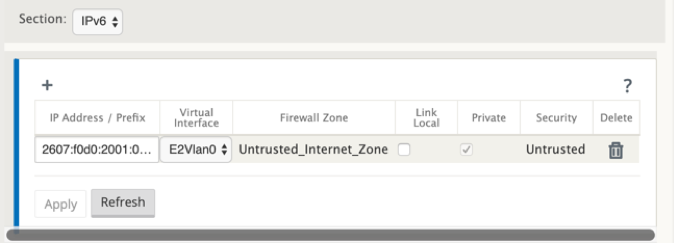
You need to add a virtual IP address for the newly created untrusted interface or you can enable SLAAC if it is a branch site. To add virtual IP address:
- Select IPv6 from the Section drop-don menu.
- Define the following fields:
- IP Address / Prefix – Provide the full host address and netmask.
- Virtual Interface – Select one of the associated virtual interfaces from the drop-down menu.
- Firewall Zone – The firewall zone for the virtual interface.
-
Link Local (Optional)- If the Link Local check box is enabled, this IPv6 Virtual IP Address can be used as the link local address for the Virtual Interface.
NOTE If the Link Local check box is not enabled, the appliance automatically generates and assign a link local address.
NOTE Neighbor Discovery Protocol (NDP) is supported by IPv6.
If both IPv4 and IPv6 Access Interfaces are defined at local and remote site, then the path is formed using only IPv6 address.
How to configure WAN links for the MCN
The next step is to configure the WAN links for the site.
-
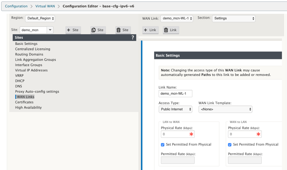
Continuing in the Sites view for the new MCN site, click the WAN Links label.

-
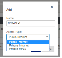
Click Add Link to the right of the WAN Links to add a new WAN link. This opens the Add dialog box.
-
(Optional) Enter a name for the WAN Link if you do not want to use the default. The default is the site name, appended with the following suffix: WL-<number>, where <number> is the number of WAN Links for this site, incremented by one.
-
Select the Access Type from the drop-down menu. The options are Public Internet, Private Intranet, or Private MPLS.
-
Click Add. This displays the WAN Links Basic Settings configuration page, and adds the new unconfigured WAN link to the page.
Only IPv6 path between two sites is formed when both IPv4 and IPv6 Access Interfaces are configured for the same WAN Link.
-
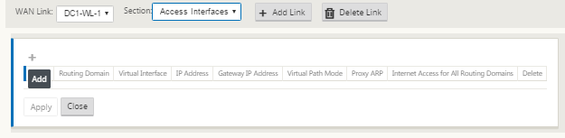
Select Access Interfaces (IPv6) from the Setting drop-down menu.
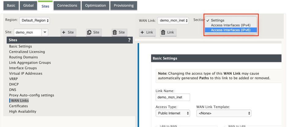
-
Define the following fields:
- Name – Provide the Access Interface name.
- Virtual Interface – Once a routing domain is selected, select one of the associated virtual interfaces from the drop-down menu.
- IP Address – Provide static IP address for the access interface endpoint on the SD-WAN.
-
Gateway IP Address – Provide the IP address of the gateway router.
NOTE You cannot configure the IP address and the gateway IP address when the virtual appliance is configured to use SLAAC mode.
-
Virtual Path Mode - Select the virtual path mode from the drop-down menu to determine the priority for virtual path traffic on this WAN link.
-
Gateway MAC Address Binding – If the Gateway MAC Address Binding check box is enabled, the source MAC address of packets received on internet or intranet services must match the gateway MAC address.
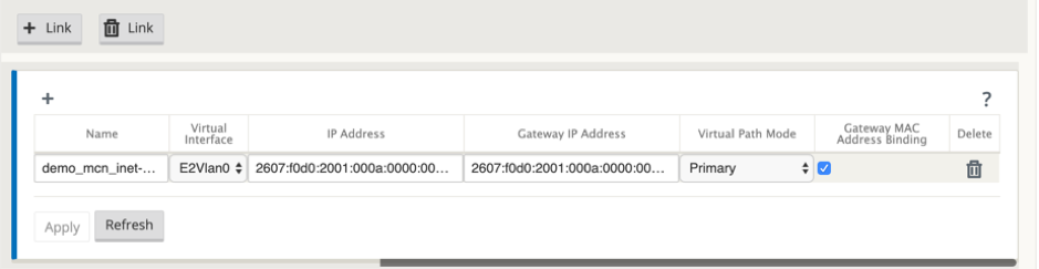
Once the IPv6 interface is created for the WAN link, you can use this interface to communicate with the Internet Service Provider (ISP).
NOTE Since the initial IPv6 offering is Virtual Path connectivity only, we cannot send LAN side IPv6 packets.
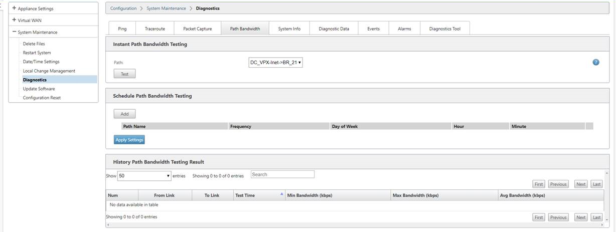
Auto Learn of bandwidth consumption
Auto learn runs on system startup and repeats every five minutes until a successful result is observed. Auto learn also runs after any WAN link configuration changes are made from the config editor.
You can execute tests manually or schedule tests in the SD-WAN GUI. Results from these tests should also apply to the permitted rate when the test is successful and auto learn is enabled.
When using auto learn on large networks, if config change restarts then all sites run tests simultaneously on the MCN, causing high bandwidth usage leading to inaccurate results. It is recommended that you schedule bandwidth tests once or twice a day, typically when traffic volume is low.
Note
Auto detection of WAN Link bandwidth, is applicable only on branches and not applicable for MCN/RCN.
- Enter the link details for the new WAN link. Configure the LAN to WAN, WAN to LAN settings. Some guidelines are as follows:
- Some Internet links might be asymmetrical.
- Misconfiguring the permitted speed can adversely affect performance for that link
- Avoid using burst speeds that surpass the Committed Rate.
- For Internet WAN links, be sure to add the Public IP Address.
-
Click the gray Advanced Settings section bar. This opens the Advanced Settings form for the link.
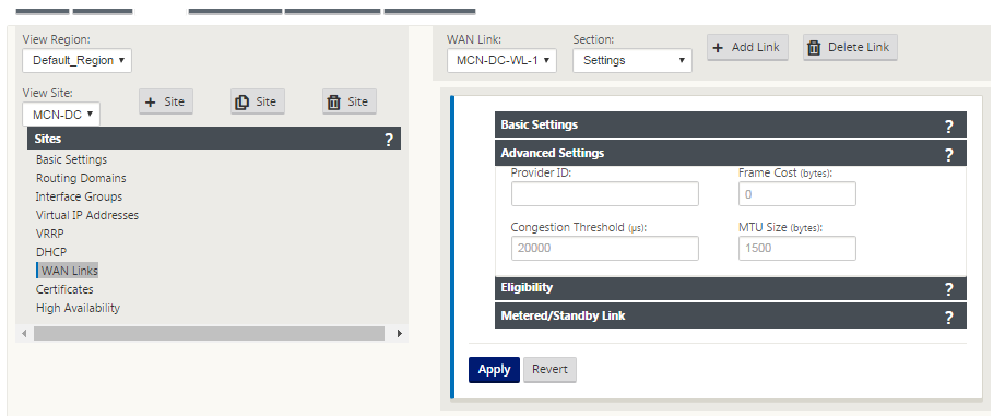
- Enter the Advanced Settings for the link:
- Provider ID – (Optional) Enter a unique ID number 1–100 to designate WAN Links connected to the same service provider. Virtual WAN uses the Provider ID to differentiate paths when sending duplicate packets.
- Frame Cost (bytes) – Enter the size (in bytes) of the header/trailer added to each packet. For example, the size in bytes of added Ethernet IPG or AAL5 trailers.
- Congestion Threshold – Enter the congestion threshold (in microseconds) after which the WAN link throttles packet transmission to avoid further congestion.
- MTU Size (bytes) – Enter the largest raw packet size (in bytes), not including the Frame Cost.
-
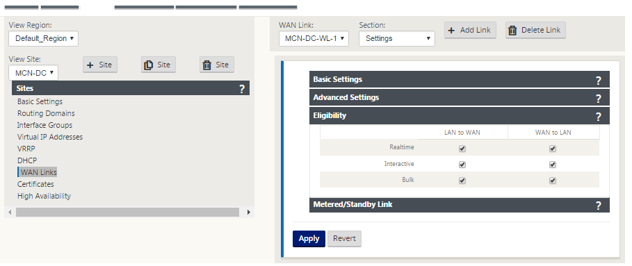
Click the gray Eligibility section bar. This opens the Eligibility settings form for the link.
-
Select the Eligibility settings for the link.
-
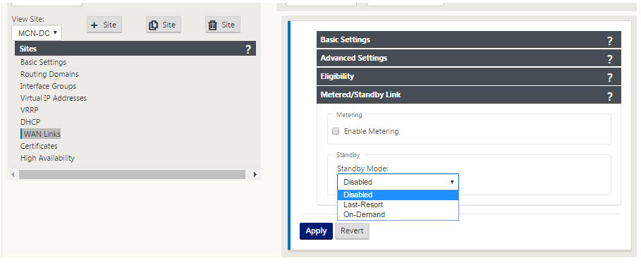
Click the gray Metered Link section bar. This opens the Metered Link settings form for the link.
-
(Optional) Select Enable Metering to enable metering for this link. This displays the Enable Metering settings fields.
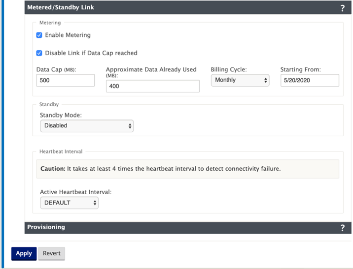
- Configure the metering settings for the link. Enter the following:
-
Data Cap (MB) – Enter the data cap allocation for the link, in megabytes.
-
Billing Cycle – Select either Monthly or Weekly from the drop-down menu.
-
Starting From – Enter the start date of the billing cycle.
-
Set Last Resort – Select this to enable this link as a link of last resort in the event of a failure of all other available links. Under normal WAN conditions, Virtual WAN sends only minimal traffic over metered links, for checking link status. However, in the event of a failure, SD-WAN can use active metered links as a last resort for forwarding production traffic.
Click Apply. This applies your specified settings to the new WAN link.
The next step is to configure the Access Interfaces for the new WAN link. An Access Interface consists of a Virtual Interface, WAN endpoint IP Address, Gateway IP Address, and Virtual Path Mode defined collectively as an interface for a specific WAN link. Each WAN link must have at least one Access Interface.
How to configure access interface:
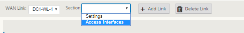
-
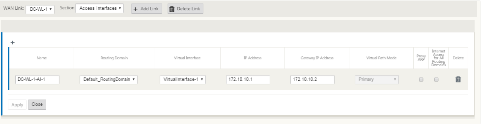
Select Access Interfaces in the WAN Link configuration page for the link. This opens the Access Interfaces view for the site.
-
Click + to add an interface. This adds a blank entry to the table and opens it for editing. Enter the Access Interfaces settings for the link. Each WAN link must have at least one Access Interface.
-
Enter the following:
- Name – This is the name by which this Access Interface is referenced. Enter a name for the new Access Interface, or accept the default. The default uses the following naming convention: WAN_link_name-AI-number: Where WAN_link_name is the name of the WAN link you are associating with this interface, and number is the number of Access Interfaces currently configured for this link, incremented by 1.
Note
If the name appears truncated, you can place your cursor in the field, then click and hold and roll your mouse right or left to see the truncated portion.
-
Virtual Interface – This is the Virtual Interface this Access Interface uses. Select an entry from the drop-down menu of Virtual Interfaces configured for this branch site.
-
Routing Domain - The routing domain which you want to choose for the Access Interface.
-
IP Address – This is the IP Address for the Access Interface endpoint from the appliance to the WAN.
-
Gateway IP Address – This is the IP Address for the gateway router.
-
Virtual Path Mode – This specifies the priority for Virtual Path traffic on this WAN link. The options are: Primary, Secondary, or Exclude. If set to Exclude, this Access Interface is used for Internet and Intranet traffic, only.
-
Proxy ARP – Select the check box to enable. If enabled, the Virtual WAN Appliance replies to ARP requests for the Gateway IP Address, when the gateway is unreachable.
- Click Apply.
You have now finished configuring the new WAN link. Repeat these steps to add and configure more WAN links for the site.
The next step is to add and configure the routes for the site.
How to configure routes for the MCN
To add and configure the routes for the site, do the following:
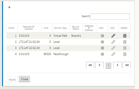
- Click the Connections view for the new MCN site and select Routes. This displays the Routes view for the site.
-
Click + to the right of Routes to add a route. This opens the Routes dialog box for editing.
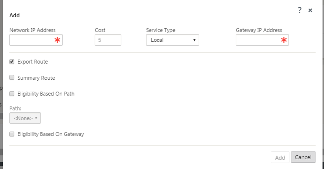
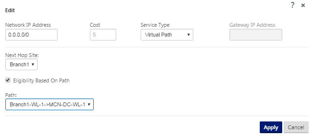
- Enter the route configuration information for the new route. Enter the following:
- Network IP Address – Enter the Network IP Address.
- Cost – Enter a weight from 1 to 15 for determining the route priority for this route. Lower-cost routes take precedence over higher-cost routes. The default value is 5.
-
Service Type – Select the service type for the route from the drop-down menu for this field.
- Virtual Path – This service manages traffic across the Virtual Paths. A Virtual Path is a logical link between two WAN links. It comprises a collection of WAN Paths combined to provide high service-level communication between two SD-WAN nodes. This is accomplished by constantly measuring and adapting to changing application demand and WAN conditions. SD-WAN Appliances measure the network on a per-path basis. A Virtual Path can be static (always exists) or dynamic (exists only when traffic between two SD-WAN Appliances reaches a configured threshold).
- Internet – This service manages traffic between an Enterprise site and sites on the public Internet. Traffic of this type is not encapsulated. During times of congestion, the SD-WAN actively manages bandwidth by rate-limiting Internet traffic relative to the Virtual Path, and Intranet traffic according to the SD-WAN configuration established by the Administrator.
- Intranet – This service manages Enterprise Intranet traffic that has not been defined for transmission across a Virtual Path. As with Internet traffic, it remains unencapsulated, and the SD-WAN manages bandwidth by rate-limiting this traffic relative to other service types during times of congestion. Under certain conditions, and if configured for Intranet Fallback on the Virtual Path, traffic that ordinarily travels by a Virtual Path may instead be treated as Intranet traffic, to maintain network reliability.
- Passthrough – This service manages traffic that is to be passed through the Virtual WAN. Traffic directed to the Passthrough Service includes broadcasts, ARPs, and other non-IPv4 traffic, as well as traffic on the Virtual WAN Appliance local subnet, configured subnets, or Rules applied by the Network Administrator. This traffic is not delayed, shaped, or modified by the SD-WAN. Therefore, you must ensure that Passthrough traffic does not consume substantial resources on the WAN links that the SD-WAN Appliance is configured to use for other services.
- Local – This service manages IP traffic local to the site that matches no other service. SD-WAN ignores traffic sourced and destined to a local route.
- GRE Tunnel – This service manages IP traffic destined for a GRE tunnel, and matches the LAN GRE tunnel configured at the site. The GRE Tunnel feature enables you to configure SD-WAN Appliances to terminate GRE tunnels on the LAN. For a route with service type GRE Tunnel, the gateway must reside in one of the tunnel subnets of the local GRE tunnel.
- LAN IPsec Tunnel – This service manages IP traffic destined for IPsec tunnel.
- Inter Routing - This service enables route leaking between Routing Domains within a site or between different sites. This eliminates the need for an edge router to handle route leaking.
- Gateway IP Address – Enter the Gateway IP Address for this route.
- Eligibility - Based on Path (check box) – (Optional) If enabled, the route does not receive traffic when the selected path is down.
- Path – This specifies the path to be used for determining route eligibility.
Depending on the “Service Type,” the following settings are displayed:
| Service Type | Service Type Settings |
|---|---|
| Virtual Path | Next Hop Site – This indicates the remote site to which Virtual Path packets are directed. |
| Internet | Export Route: Enable/Disable to export routes to other connected sites, Eligibility based on path |
| Intranet | Export route, Intranet service, Eligibility based on path, Eligibility based on tunnel |
| Passthrough | Eligibility based on path |
| Local | Export route, Summary route, Eligibility based on path |
| GRE Tunnel | Export route, Eligibility based on path, Eligibility based on Gateway |
| IPsec Tunnel | Export route, Eligibility based on path, IPsec Tunnel, Eligibility based on tunnel |
| Discard | Export route, Summary route |
| Inter Routing | Inter Routing Domain Service |
- Click Apply.
Note
After you click Apply, audit warnings might appear indicating that further action is required. A red dot or goldenrod delta icon indicates an error in the section where it appears. You can use these warnings to identify errors or missing configuration information. Roll your cursor over an audit warning icon to display a short description of the errors in that section. You can also click the dark gray Audits status bar (bottom of page) to display a complete list of all audit warnings.
You can also edit configured routes as following.
To add more routes for the site, click + to the right of the Routes branch, and proceed as above.
You have now finished entering the primary configuration information for the new MCN site. The following two sections provide instructions for more optional steps:
-
Configuring High Availability (HA) for the MCN Site (Optional).
-
Enabling and Configuring Virtual WAN Security and Encryption (Optional).
If you do not want to configure these features now, you can proceed directly to the section Naming, Saving, and Backing Up the MCN Site Configuration.