High availability
This topic covers the High Availability (high availability) deployments and configurations supported by SD-WAN appliances (Standard Edition and Premium (Enterprise) Edition).
Citrix SD-WAN appliances can be deployed in high availability configuration as a pair of appliances in Active/Standby roles. There are three modes of high availability deployment:
-
Parallel Inline high availability
-
Fail-to-Wire high availability
-
One-Arm high availability
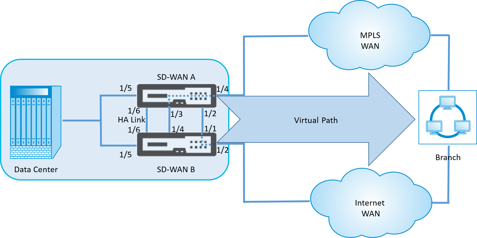
These high availability deployment modes are similar to the Virtual Router Redundancy Protocol (VRRP) and use a proprietary SD-WAN protocol. Both Client Nodes (Clients) and Master Control Nodes (MCNs) within an SD-WAN network can be deployed in a high availability configuration. The primary and secondary appliance must be the same platform models.
In high availability configuration, one SD-WAN appliance at the site is designated as the Active appliance. The Standby appliance monitors the Active appliance. Configuration is mirrored across both appliances. If the Standby appliance loses connectivity with the Active appliance for a defined period, the Standby appliance assumes the identity of the Active appliance and takes over the traffic load. Depending on the deployment mode, this fast failover has minimal impact on the application traffic passing through the network.
High availability deployment modes
One-Arm mode:
In One-Arm mode, the high availability appliance pair is outside of the data path. Application traffic is redirected to the appliance pair with Policy Based Routing (PBR). One-Arm mode is implemented when a single insertion point in the network is not feasible or to counter the challenges of fail-to-wire. The Standby appliance can be added to the same VLAN or subnet as the Active appliance and the router.
In One-Arm mode, it is recommended that the SD-WAN appliances do not reside in the data network subnets. The virtual path traffic does not have to traverse the PBR and avoids route loops. The SD-WAN appliance and router have to be directly connected, either through an Ethernet port or be in the same VLAN.
-
IP SLA monitoring for fall back:
The active traffic flows even if the virtual path is down, as long as one of the SD-WAN appliances is active. The SD-WAN appliance redirects traffic back to the router as Intranet traffic. However, if both active/standby SD-WAN appliances become inactive, the router tries to redirect traffic to the appliances. IP SLA monitoring can be configured at the router to disable PBR, if the next appliance is not reachable. It allows the router to fall back to perform a route lookup and forward packets appropriately.
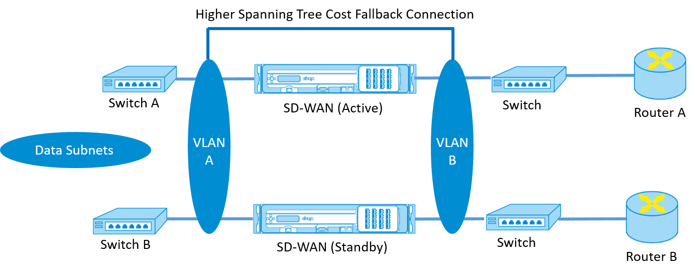
Parallel Inline high availability mode:
In Parallel Inline high availability mode, the SD-WAN appliances are deployed alongside each other, inline with the data path. Only one path through the Active appliance is used. It is important to note that bypass interface groups are configured to be fail-to-block to avoid bridging loops during a failover.
The high availability state can be monitored through the inline interface groups, or through a direct connection between the appliances. External Tracking can be used to monitor the reachability of the upstream or downstream network infrastructure. For example; switch port failure to direct high availability state change, if needed.
If both active and standby SD-WAN appliances are disabled or fail, a tertiary path can be used directly between the switch and router. This path must have a higher spanning tree cost than the SD-WAN paths so that it is not used under normal conditions. Failover in parallel inline high availability mode depends on the configured failover time, the default failover time is 1000 ms. However, a failover has a traffic impact of 3-5 seconds. Fall back to the tertiary path impacts traffic for the duration of spanning tree re-convergence. If there are out of path connections to other WAN Links, both appliances must be connected to them.
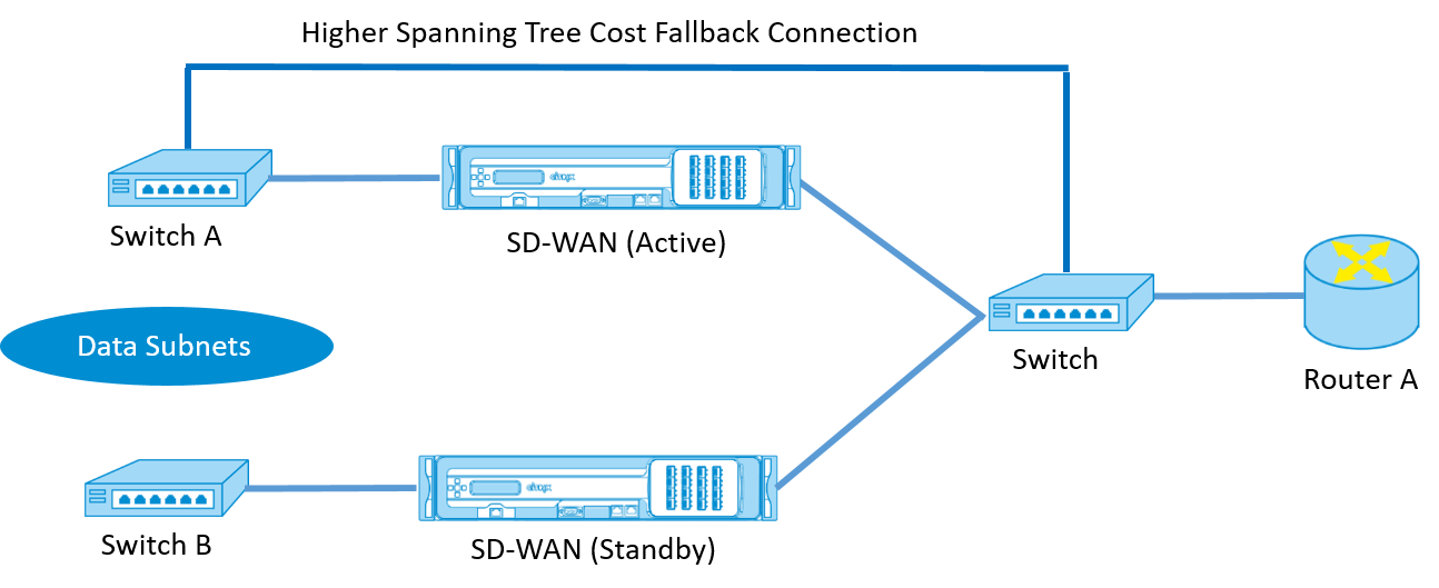
In more complex scenarios, where multiple routers might be using VRRP, non-routable VLANs are recommended to ensure that the LAN side switch and routers are reachable at layer 2.
Fail-to-Wire mode:
In fail-to-wire mode, the SD-WAN appliances are inline in the same data path. The bypass interface groups must be in the fail-to-wire mode with the Standby appliance in a passthrough or bypass state. A direct connection between the two appliances on a separate port must be configured and used for the high availability interface group.
Note
High availability switchover in fail-to-wire mode takes approximately 10–12 seconds because of the delay in ports to recover from Fail-to-Wire mode.
If the high availability connection between the appliances fails, both appliances go into Active state and cause a service interruption. To mitigate the service interruption, assign multiple high availability connections so that there is no single point of failure.
It is imperative that in high availability Fail-to-Wire Mode, a separate port is used in the hardware appliance pairs for the high availability control exchange mechanism to help with state convergence.
Because of a physical state change when the SD-WAN appliances switch over from Active to Standby, failover can cause partial loss of connectivity depending on how long the auto-negotiation takes on the Ethernet ports.
The following illustration shows an example of the Fail-to-Wire deployment.
The One-Arm high availability configuration or Parallel Inline high availability configuration is recommended for data centers or Sites that forward a high volume of traffic to minimize disruption during failover.
If minimal loss of service is acceptable during a failover, then Fail-to-Wire high availability mode is a better solution. The Fail-to-Wire high availability mode protects against appliance failure and parallel inline high availability protects against all failures. In all scenarios, high availability is valuable to preserve the continuity of the SD-WAN network during a system failure.
Configure high availability
To configure high availability:
-
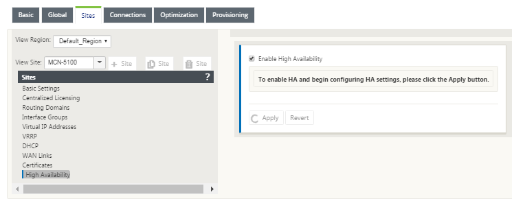
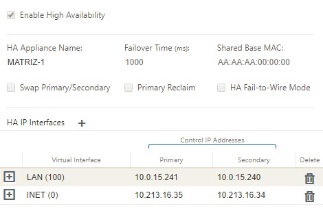
In the Configuration Editor, navigate to Sites > site name > High Availability. Select Enable High Availability, and click Apply.
-
Type values for the following parameter:
-
High availability Appliance Name: The name of the high availability (secondary) appliance.
-
Failover Time: The wait time (in milliseconds) after contact with the primary appliance is lost, before the standby appliance becomes active.
-
Shared Base MAC: The shared MAC address for the high availability pair appliances. When a failover occurs, the secondary appliance has the same virtual MAC addresses as the failed primary appliance.
-
Swap Primary/Secondary: When selected, if both appliances in the high availability pair come up simultaneously, the secondary appliance becomes the primary appliance, and takes precedence.
-
-
Primary Reclaim: When selected, the designated primary appliance reclaims control upon restart after a failover event.
-
High availability Fail-to-Wire Mode: Select to enable Fail-to-Wire high availability deployment mode.
Note
For hypervisor and cloud based platforms choose the Disable Shared Base MAC option to disable the shared virtual MAC address.
For hypervisor based platforms ensure that the promiscuous mode is enabled on the hypervisors to allow packet sourcing from high availability shared MAC address. If promiscuous mode is not enabled, you can enable the Disable Shared Base MAC option.
Click + next to high availability IP Interfaces to configure interface groups. Type Values for the following parameters:
-
Virtual Interface – The Virtual Interface to be used for communication between the appliances in the high availability pair. It monitors the Active appliance for reachability. For One-Arm high availability mode, only one interface group is required.
-
Primary – The unique Virtual IP address for the primary appliance. The secondary appliance uses the Primary Virtual IP address to communicate with the primary appliance.
-
Secondary – The unique Virtual IP address for the secondary appliance. The primary appliance uses the Secondary Virtual IP address to communicate with the secondary appliance.
Click + to the left of the new high availability IP Interfaces entry. In the External Tracking IP Address field, type the IP address of the external device that responds to ARP requests to determine the state of the primary appliance and then click Apply.
Note:
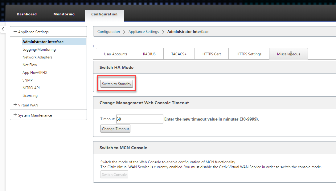
You can also manually trigger a HA switchover from the appliance. Navigate to Configuration > Appliance Settings > Administrator Interface > Miscellaneous. In the Switch HA Mode section, click Switch to Standby or Switch to Active depending on the HA appliance.
Monitoring
To monitor high availability configuration:
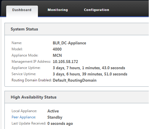
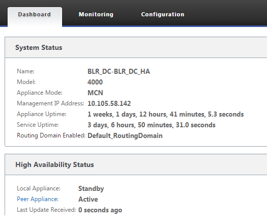
Log in to the SD-WAN web management interface for the Active and Standby appliance’s for which high availability is implemented. View high availability status under the Dashboard tab.
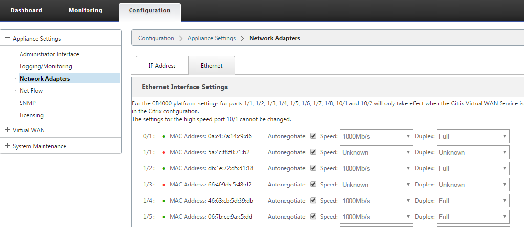
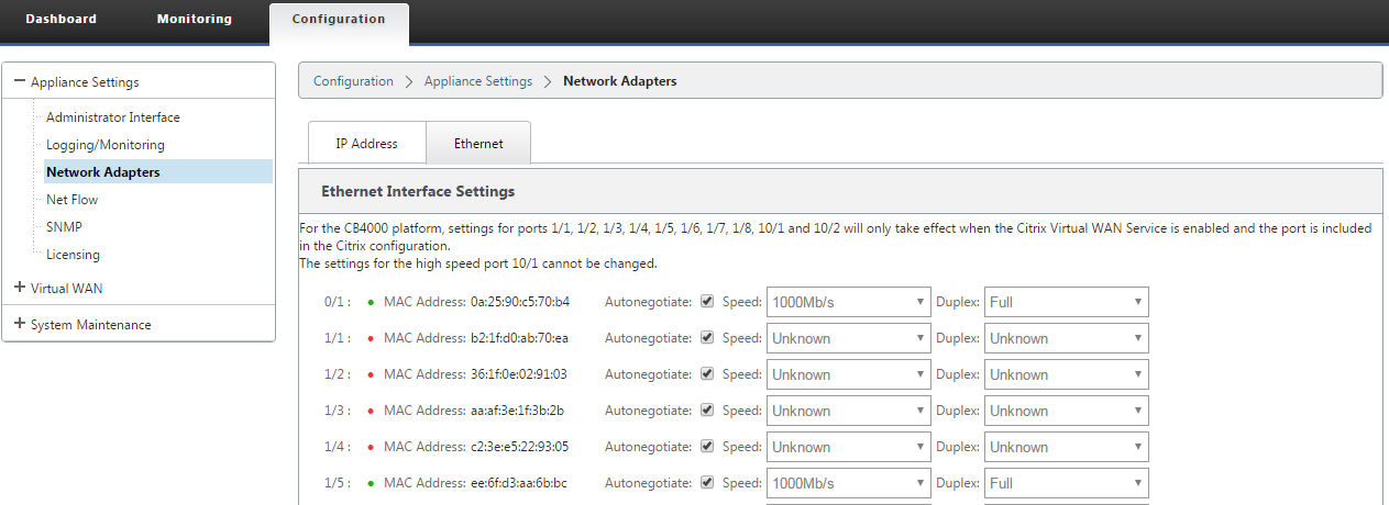
For Network Adapter details of Active and Standby high availability appliances, navigate to Configuration > Appliance Settings > Network Adapters > Ethernet tab.
Troubleshooting
Perform the following troubleshooting steps while configuring the SD-WAN appliance in High Availability (HA) mode:
-
The primary reason for split-brain issue is due to communication problem between the HA appliances.
- Check if any issue with the connectivity (such as, the ports on both the SD-WAN appliance are up or down) between the SD-WAN appliances.
- Must disable SD-WAN service on one of the SD-WAN appliances to ensure only one SD-WAN appliance be active.
-
You can verify the HA related logs that is logged into SDWAN_common.log file.
NOTE All the HA related logs is logged with the key word racp.
- You can verify the port related events in SDWAN_common.log file (such as, the HA enabled ports goes down or up).
- For every HA state change, one SD-WAN event is logged. So if the logs are rolled over, you can verify the event logs to get the event details.