Configure branch node
To add a new branch site to the Sites table and begin configuring the site, do the following:
Note
If you logged out of the MCN after creating and saving the new configuration package, you will need to log back in and reopen the configuration before you can continue. To do so, click Open in the Configuration Editor menu bar (top of page area). This displays a dialog box for selecting the configuration you want to change.
-
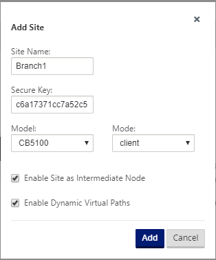
Continuing in the Configuration Editor, click Add in the Sites bar to begin adding and configuring the new branch site. The Add Site dialog box appears.
-
Type the following site information.
Note
Entries cannot contain spaces and must be in Linux format.
- Site Name – type a name for the site.
- Appliance Name – type the name you want to assign to the appliance.
- Secure Key – This is a hexadecimal key of 8–32 digits used for encryption and membership verification in the SD-WAN Appliance. By default, this field is prefilled with an automatically generated security key. Accept the default or type a custom key-in hexadecimal format.
- Model – Select the appliance model from the drop-down menu.
- Mode – Select client as the mode.
-
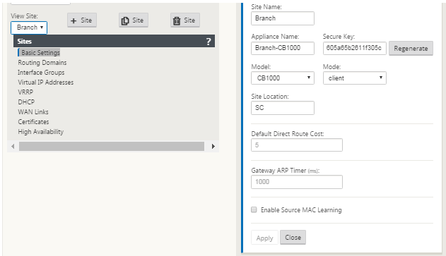
Click Add to add the site. The new site is added to the Sites tree, and opens the Basic Settings configuration form for the site.
-
Type the basic settings for the site, and click Apply.
The next step is to add and configure the Interface Groups for the new branch site.
How to configure interface groups for the branch
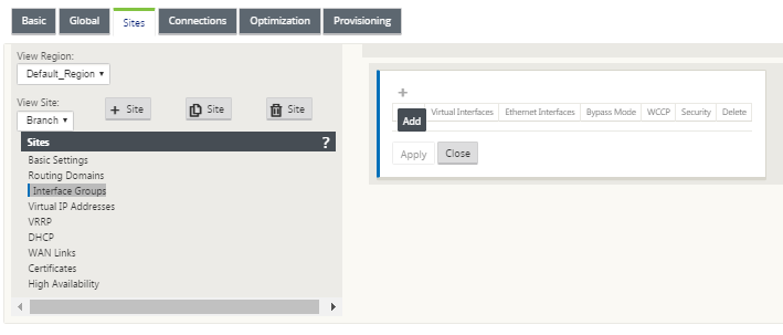
To add Interface Group to the new branch site, do the following:
-
Continuing in the Sites view of the Configuration Editor, select the branch site from the View Site drop down menu. This opens configuration view for the site you selected.
-
Click + to add the Virtual Interface Group. A new blank Virtual interface group entry is added to the table and opens for editing.
-
Click + to the right of Virtual Interfaces. A new blank group entry is added to the table and opens for editing.
-
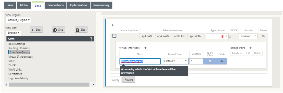
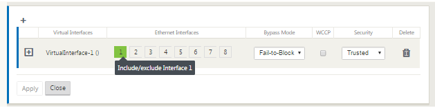
Select the Ethernet Interfaces to include in the group.
Under Ethernet Interfaces, click an interface to include/exclude that interface. You can select any number of interfaces to include in the group.
-
Select the Bypass Mode from the drop-down menu (no default).
The Bypass Mode specifies the behavior of bridge-paired interfaces in the Virtual Interface Group, in the event of an appliance or service failure or restart. The options are: Fail-to-Wire or Fail-to-Block.
-
Select the Security Level from the drop-down menu.
This specifies the security level for the network segment of the Virtual Interface Group. The options are: Trusted or Untrusted. Trusted segments are protected by a firewall (default is Trusted).
-
Click + at the left edge of the Virtual Interface you added. This displays the Virtual Interfaces table.
-
Click + to the right of Virtual Interfaces. The Name, Firewall Zone, and VLAN ID ids appear.
-
Type the Name and VLAN ID for this Virtual Interface Group.
-
Name – The name by which this Virtual Interfaces are referenced.
-
Firewall Zone - Select a firewall zone from the drop-down menu.
-
VLAN ID – The ID for identifying and marking traffic to and from the Virtual Interface. Use an ID of 0 (zero) for native/untagged traffic.
-
-
Click + to the right of Bridge Pairs. A new Bridge Pairs entry is added and opens for editing.
-
Select the Ethernet interfaces to be paired from the drop-down menus. To add more pairs, click + next to Bridge Pairs again.
-
Click Apply. Your settings are applied and added to the new Virtual Interface Group of the table.
Note
At this stage, you see a yellow delta Audit Alert icon, to the right of the new Virtual Interface Group entry. This is because you have not yet configured any Virtual IP Addresses (VIPs) for the site. For now, you can ignore this alert, as it is resolved automatically when you have properly configured the Virtual IPs for the site.
-
To add more Virtual Interface Groups, click + to the right of the Interface Groups branch, and proceed as above.
How to configure virtual IP address for the branch site
The next step is to configure the Virtual IP Addresses for the site, and assign them to the appropriate group.
-
Continuing in the Sites view for the new Branch site, click + to the left of the Virtual IP Addresses. This displays the Virtual IP Addresses table for the new site.
-
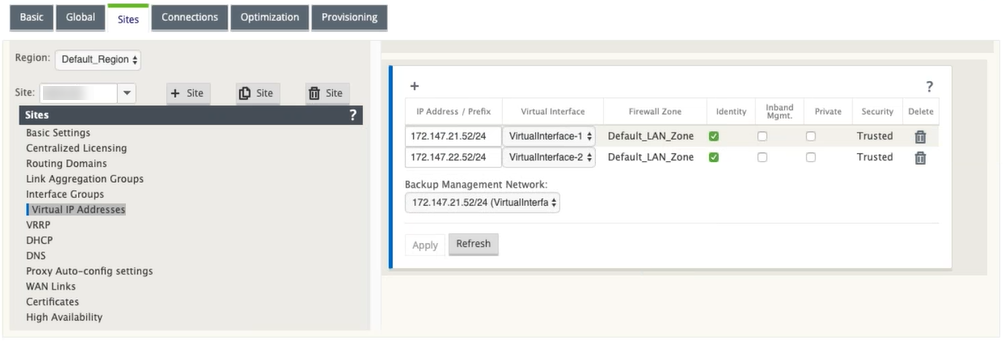
Click + to the right of Virtual IP Addresses to add an address. The form for adding and configuring a new Virtual IP Address appears.
-
Type the IP Address / Prefix information, and select the Virtual Interface with which the address is associated. The Virtual IP Address must include the full host address and netmask.
-
Select the desired settings for the Virtual IP address; such as the Firewall Zone, Identity, Private, and Security.
-
Select Inband Mgmt to allow the virtual IP address to connect to management services such as web UI and SSH.
Note:
The interface should be of security type Trusted and Identity enabled.
-
Select a virtual IP as a Backup Management Network. This allows you to use the virtual IP address for management if the management port is not configured with a default gateway.
-
Click Apply. The address information to the site is added and includes it in the site Virtual IP Addresses table.
-
To add more Virtual IP Addresses, click + to the right of the Virtual IP Addresses, and proceed as above.
How to configure WAN links for the branch
The next step is to configure the WAN links for the site.
-
Continuing in the Sites view for the new Branch site, click the WAN Links label.
-
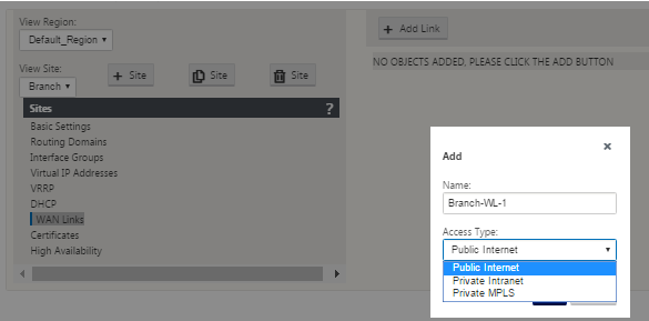
Click Add Link to the right of the WAN Links to add a new WAN link. The Add dialog box appears.
-
(Optional) type a name for the WAN Link if you do not want to use the default.
The default is the site name, appended with the following suffix:
-WL-<number>
Where <number> is the number of WAN Links for this site, incremented by one.
-
Select the Access Type from the drop-down menu.
The options are Public Internet, Private Intranet, or Private Multiprotocol Label Switching.
-
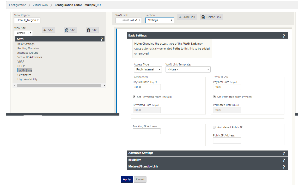
Click Add. The WAN Links Basic Settings configuration page appears and adds the new unconfigured WAN link to the page.
-
Type the link details for the new WAN link. Configure the LAN to WAN, WAN to LAN settings.
Some guidelines are as follows:
-
Some Internet links might be asymmetrical. Misconfiguring the permitted speed can adversely affect performance for that link.
-
Avoid using burst speeds that surpass the Committed Rate.
-
For Internet WAN links, be sure to add the Public IP Address.
-
-
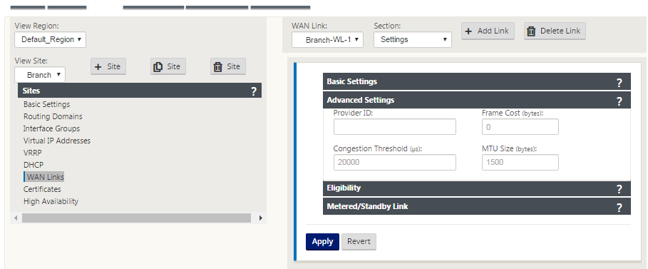
Click the gray Advanced Settings section bar. This opens the Advanced Settings form for the link.
-
Type the Advanced Settings for the link.
-
Provider ID – (Optional) type a unique ID number 1–100 to designate WAN Links connected to the same service provider. Virtual WAN uses the Provider ID to differentiate paths when sending duplicate packets.
-
Frame Cost (bytes) – type the size (in bytes) of the header/trailer added to each packet. For example, the size in bytes of added Ethernet IPG or AAL5 trailers.
-
Congestion Threshold – type the congestion threshold (in microseconds) after which the WAN link throttles packet transmission to avoid further congestion.
-
MTU Size (bytes) – type the largest raw packet size (in bytes), not including the Frame Cost.
-
-
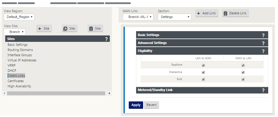
Click the gray Eligibility section bar. This opens the Eligibility settings form for the link.
-
Select the Eligibility settings for the link.
-
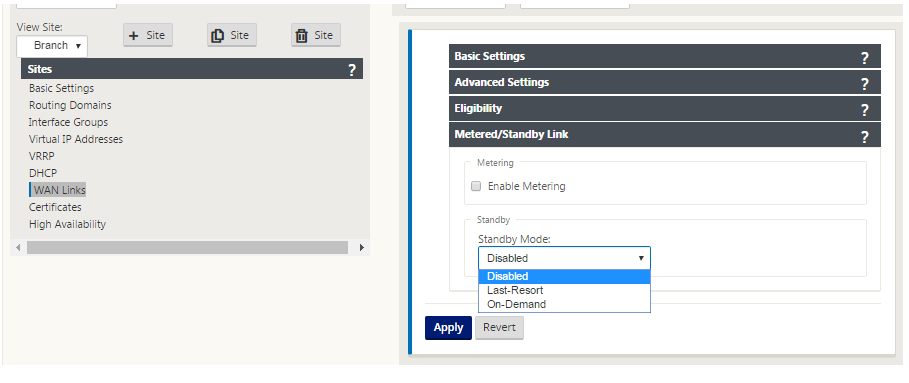
Click the gray Metered Link section bar. This opens the Metered Link settings form for the link.
-
(Optional) Select Enable Metering to enable metering for this link. This displays the Enable Metering settings fields.
-
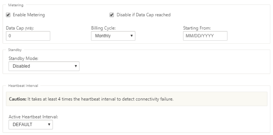
Configure the metering settings for the link. Type the following:
- Data Cap (MB) – type the data cap allocation for the link, in MB.
- Billing Cycle – Select either Monthly or Weekly from the drop-down menu.
- Starting From – type the start date of the billing cycle.
- Set Last Resort – Select this to enable this link as a link of last resort in the event of a failure of all other available links. Under normal WAN conditions, Virtual WAN sends only minimal traffic over metered links, for checking link status. However, in the event of a failure, SD-WAN can use active metered links as a last resort for forwarding production traffic.
-
Click Apply. This applies your specified settings to the new WAN link.
The next step is to configure the Access Interfaces for the new WAN link. An Access Interface consists of a Virtual Interface, WAN endpoint IP Address, Gateway IP Address, and Virtual Path Mode defined collectively as an interface for a specific WAN link. Each WAN link must have at least one Access Interface.
Note
An option to auto-provision shares by considering remote bandwidth is added to configure WAN links. The Set Provisioning using Remote Bandwidth option enables users with large networks and diverse bandwidth configurations to manage bandwidth provisioning for datacenter sites in a dynamic way.
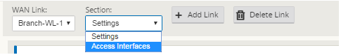
-
Select Access Interfaces in the WAN Link configuration page for the link. This opens the Access Interfaces view for the site.
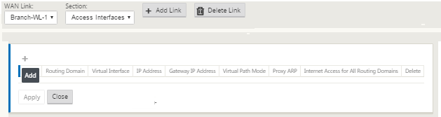
-
Click + to add an interface. A blank entry to the table is added and opens for editing. Type the Access Interfaces settings for the link.
Note
Each WAN link must have at least one Access Interface.
-
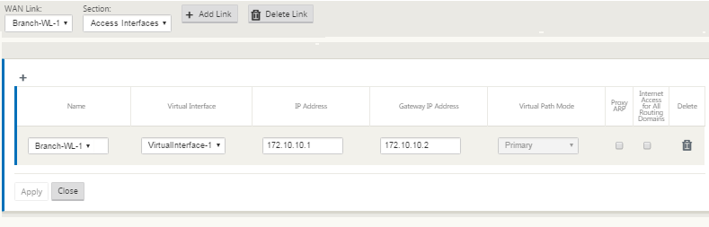
Type the following:
-
Name: This is the name by which this Access Interface is referenced. Type a name for the new Access Interface, or accept the default. The default uses the following naming convention:
WAN_link_name-AI-number
Where WAN_link_name is the name of the WAN link you are associating with this interface, and number is the number of Access Interfaces currently configured for this link, incremented by 1.
Note
If the name appears truncated, you can place your cursor in the field, then click and hold and roll your mouse right or left to see the truncated portion.
- Virtual Interface – The Virtual Interface this Access Interface uses. Select an entry from the drop-down menu of Virtual Interfaces configured for this branch site.
- IP Address – The IP Address for the Access Interface endpoint from the appliance to the WAN.
- Gateway IP Address - This is the IP Address for the gateway router.
- Virtual Path Mode – The priority for Virtual Path traffic on this WAN link. The options are: Primary, Secondary, or Exclude. If set to Exclude, this Access Interface is used for Internet and Intranet traffic, only.
- Proxy ARP – Select the checkbox to enable. If enabled, the Virtual WAN Appliance replies to ARP requests for the Gateway IP Address, when the gateway is unreachable.
-
-
Click Apply.
You have now finished configuring the new WAN link. Repeat these steps to add and configure extra WAN links for the site.
The next step is to add and configure the routes for the site.
How to configure routes for the branch
To add and configure the routes for the site, do the following:
-
Click the Connections view for the new Branch site and select Routes. This displays the Routes view for the site.
-
Click + to the right of Routes to add a route. This opens the Routes dialog box for editing.
-
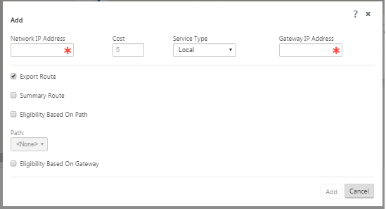
Type the route configuration information for the new route.
-
Network IP Address – type the Network IP Address.
-
Cost – type a weight from 1 to 15 for determining the route priority for this route. Lower-cost routes take precedence over higher-cost routes. The default value is 5.
-
Service Type – Select the service type for the route from the drop-down menu for this field. The options are as follows:
-
Virtual Path – This service manages traffic across the Virtual Paths. A Virtual Path is a logical link between two WAN links. It comprises a collection of WAN Paths combined to provide high service-level communication between two SD-WAN nodes. This is done by constantly measuring and adapting to changing application demand and WAN conditions. SD-WAN Appliances measure the network on a per-path basis. A Virtual Path can be static (always exists) or dynamic (exists only when traffic between two SD-WAN Appliances reaches a configured threshold).
-
Internet – This service manages traffic between an Enterprise site and sites on the public Internet. Traffic of this type is not encapsulated. During times of congestion, the SD-WAN actively manages bandwidth by rate-limiting Internet traffic relative to the Virtual Path, and Intranet traffic according to the SD-WAN configuration established by the Administrator.
-
Intranet – This service manages Enterprise Intranet traffic that has not been defined for transmission across a Virtual Path. As with Internet traffic, it remains unencapsulated, and the SD-WAN manages bandwidth by rate-limiting this traffic relative to other service types during times of congestion. Under certain conditions, and if configured for Intranet Fallback on the Virtual Path, traffic that ordinarily travels with a Virtual Path can instead be treated as Intranet traffic, to maintain network reliability.
-
Passthrough – This service manages traffic that is to be passed through the Virtual WAN. Traffic directed to the Passthrough Service includes broadcasts, ARPs, and other non-IPv4 traffic, and traffic on the Virtual WAN Appliance local subnet, configured subnets, or Rules applied by the Network Administrator. This traffic is not delayed, shaped, or changed by the SD-WAN. Therefore, you must ensure that Passthrough traffic does not consume substantial resources on the WAN links that the SD-WAN Appliance is configured to use for other services.
-
Local – This service manages IP traffic local to the site that matches no other service. SD-WAN ignores traffic sourced and destined to a local route.
-
GRE Tunnel – This service manages IP traffic destined for a GRE tunnel, and matches the LAN GRE tunnel configured at the site. The GRE Tunnel feature enables you to configure SD-WAN Appliances to end GRE tunnels on the LAN. For a route with service type GRE Tunnel, the gateway must reside in one of the tunnel subnets of the local GRE tunnel.
-
LAN IPsec Tunnel – This service manages IP traffic destined for IPsec tunnel.
-
Gateway IP Address – type the Gateway IP Address for this route.
-
Eligibility Based on Path (checkbox) – (Optional) If enabled, the route does not receive traffic when the selected path is down.
-
Path – This specifies the path to be used for determining route eligibility.
-
-
Click Apply.
Note
After you click Apply, audit warnings might appear indicating that further action is required. A red dot or goldenrod delta icon indicates an error in the section where it appears. You can use these warnings to identify errors or missing configuration information. Roll your cursor over an audit warning icon to display a short description of the errors in that section. You can also click the dark gray Audits status bar (bottom of page) to display a complete list of all audit warnings.
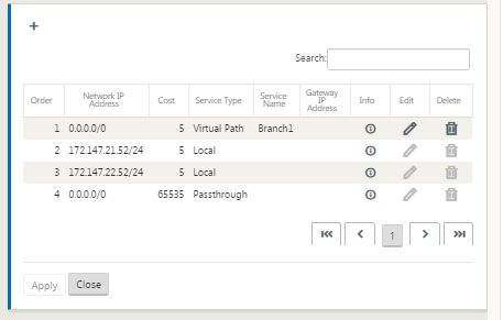
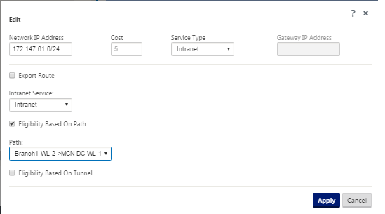
You can also edit configured routes as shown below.
You have now completed the required steps for configuring a client site. There are also some additional, optional steps you can choose to complete, before proceeding with the next phase of the deployment. A list of these steps and links to instructions are provided below. If you do not want to configure these features now, you can proceed directly to Preparing the SD-WAN Appliance Packages on the MCN.
The optional steps are as follows:
-
Configure High Availability – High Availability is a configuration in which two Virtual WAN Appliances at a site serve in an Active/Standby partnership capacity for redundancy purposes. If you are not implementing High Availability for this site, you can skip this step. For instructions, see Configuring High Availability (high availability) for the Branch Site (Optional).
-
Clone the new branch site – You have the option of cloning the branch site you configured, and using that as a template for adding another site. The appliance models for the original site and the clone must be the same. For instructions, see Cloning the Branch Site (Optional).
-
Configure WAN Optimization – If your Citrix SD-WAN Virtual WAN license includes WAN Optimization features, you have the option of enabling and adding these features to your configuration. To do so, you must complete the Optimization section in the Configuration Editor, and save the changed configuration.
Save configuration
The next step is to save the completed Sites configuration. The configuration is saved to your workspace on the local appliance.
Warning
If the console session times out or you log out of the Management Web Interface before saving your configuration, any unsaved configuration changes are lost. You must then log back into the system, and repeat the configuration procedure from the beginning. For that reason, it is recommended that you save the configuration package often, or at key points in the configuration. Note
As an extra precaution, it is recommended that you use Save As, rather than Save, to avoid overwriting the wrong configuration package.
After saving the configuration file, you have the option to log out of the Management Web Interface and continue the configuration process later. However, if you log out, you need to reopen the saved configuration when you resume. Instructions are provided in the section under Configure MCN; Loading a Saved Configuration Package into the Configuration Editor.
To save the current configuration package, do the following:
-
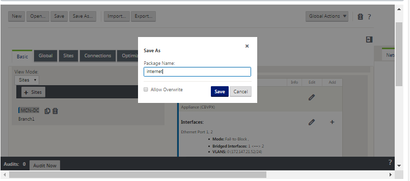
Click Save As (at the top of the Configuration Editor middle pane). This opens the Save As dialog box.
-
Type the configuration package name. Click Save.
Note
If you are saving the configuration to an existing configuration package, be sure to select Allow Overwrite before saving.
The next step is to configure the Virtual Paths and Virtual Path Service between the MCN and the client sites. Instructions are provided in the Configuring the Virtual Path Service between the MCN and Client Sites.
Renaming branch site
After renaming the branch site, you need to upload new configuration package to the network.
-
From the MCN, stage network with new configuration containing the renamed branch site.
-
Download the staging package for the renamed branch site.
-
On the MCN, select Activate Staged network. This disables the renamed site and the site becomes unavailable.
-
Navigate to the branch Local Change Management page.
-
Upload the package downloaded earlier. Click Next and then click Activate.
Renaming branch site with high availability
To upload new configuration after renaming a branch site enabled with high availability:
-
From the MCN, stage network with new configuration that contains the renamed branch site.
-
Download the staging package for both the active and high availability appliance with renamed branch site.
-
On the MCN, select Activate Staged for network. This disables the renamed site and the site becomes unavailable.
-
Navigate to the active appliance at the branch. Go to the Local Change Management page.
-
Upload the package downloaded earlier. Click Next and then click Activate.
-
Repeat steps 4 (a) and 4 (b) for the standby appliance.