-
Configuration guide for Citrix Virtual Apps and Desktops workloads
-
Citrix SD-WAN Orchestrator on-premises configuration on Citrix SD-WAN appliance
-
-
Rules by IP address and port number
-
-
This content has been machine translated dynamically.
Dieser Inhalt ist eine maschinelle Übersetzung, die dynamisch erstellt wurde. (Haftungsausschluss)
Cet article a été traduit automatiquement de manière dynamique. (Clause de non responsabilité)
Este artículo lo ha traducido una máquina de forma dinámica. (Aviso legal)
此内容已经过机器动态翻译。 放弃
このコンテンツは動的に機械翻訳されています。免責事項
이 콘텐츠는 동적으로 기계 번역되었습니다. 책임 부인
Este texto foi traduzido automaticamente. (Aviso legal)
Questo contenuto è stato tradotto dinamicamente con traduzione automatica.(Esclusione di responsabilità))
This article has been machine translated.
Dieser Artikel wurde maschinell übersetzt. (Haftungsausschluss)
Ce article a été traduit automatiquement. (Clause de non responsabilité)
Este artículo ha sido traducido automáticamente. (Aviso legal)
この記事は機械翻訳されています.免責事項
이 기사는 기계 번역되었습니다.책임 부인
Este artigo foi traduzido automaticamente.(Aviso legal)
这篇文章已经过机器翻译.放弃
Questo articolo è stato tradotto automaticamente.(Esclusione di responsabilità))
Translation failed!
Rules by IP address and port number
Rules by IP address and port number feature helps you to create rules for your network and take certain Quality of Service (QoS) decisions based on the rules. You can create custom rules for your network. For example, you can create a rule as – If source IP address is 172.186.30.74 and destination IP address is 172.186.10.89, set Transmit mode as Persistent Path and LAN to WAN Class as 10(realtime_class)”.
Using the configuration editor, you can create rules for traffic flow and associate the rules with applications and classes. You can specify criteria to filter traffic for a flow, and can apply general behavior, LAN to WAN behavior, WAN to LAN behavior, and packet inspection rules.
You can create rules locally at a site level or at the global level. If more than one site requires the same rule, you can create a template for rules globally under Global > Virtual Path Default Sets > Rules. The template can then be attached to the sites where the rules need to be applied. Even if a site is associated with the globally created rule template, you can create site specific rules. In such cases, site specific rules take precedence and override the globally created rule template.
Create rules by IP address and port number
-
In the SD-WAN Configuration Editor, navigate to Global > Virtual Path Default Sets.
Note
You can create rules at site level by navigating to Sites > Connections > Virtual Paths > Rules.
-
Click Add Default Set, enter a name for the default set, and click Add. In the Section field, select Rules and click +.
-
In the Order field, enter the order value to define when the rule is applied in relation to other rules.
-
In the Rule Group Name field, select a rule group. The statistics for rules with the same rule group will be grouped and can be viewed together.
For viewing rule groups, navigate to Monitoring > Statistics, and in the Show field select Rule Groups.
You can also add custom applications. For more information, see Add Rule Groups and Enable MOS.
-
In the Routing Domain field, choose one of the configured routing domains.
-
You can define rule matching criteria to filter services based on the parameters listed as follows. After the filtering, the rule settings are applied to the services matching these criteria.
-
Source IP Address: Source IP address and the subnet mask to match against the traffic.
-
Destination IP Address: Destination IP address and the subnet mask to match against the traffic.
Note
If the Dest=Src check box is selected, the source IP address will also be used for the destination IP address.
-
Protocol: Protocol to match against the traffic.
-
Source Port: Source port number or port range to match against the traffic.
-
Destination Port: Destination port number or port range to match against the traffic.
Note
If the Dest=Src check box is selected, the source port will also be used for the destination port.
-
DSCP: The DSCP tag in the IP header to match against the traffic.
-
VLAN: The VLAN ID to match against the traffic.
-
-
Click the add (+) icon next to the new rule.
-
Click Initialize Properties Using Protocol to initialize the rule properties by applying the rule defaults and recommended settings for the protocol. This populates the default rule settings. You can also customize the settings manually, as shown in the following steps.
-
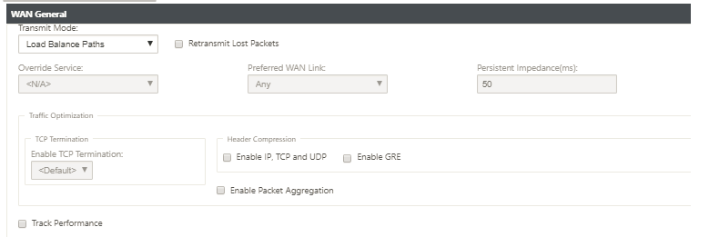
Click the WAN General tile to configure the following properties.
-
Transmit Mode: Select one of the following transmit modes.
-
Load Balance Path: Traffic for the flow will be balanced across multiple paths for the service. Traffic is sent through the best path until that path is used. Leftover packets are sent through the next best path.
-
Persistent Path: Traffic for the flow remains on the same path until the path is no longer available.
-
Duplicate Path: Traffic for the flow is duplicated across multiple paths, increasing reliability.
-
Override Service: Traffic for the flow overrides to a different service. In the Override Service field, select the service type to which the service overrides. For example, a virtual path service can override to an intranet, internet, or pass-through service.
-
-
Retransmit Lost Packets: Send traffic that matches this rule to the remote appliance over a reliable service and retransmit lost packets.
-
Enable TCP Termination: Enable TCP termination of traffic for this flow. The round-trip time for acknowledgment of packets is reduced, and therefore improves throughput.
-
Preferred WAN Link: The WAN link that the flows should use first.
-
Persistent Impedance: The minimum time in milliseconds for which the traffic would remain in the same path, until the wait time on which the path is longer than the configured value.
-
Enable IP, TCP, and UDP: Compress headers in IP, TCP, and UDP packets.
NOTE
IPv6 packets do not support header compression.
-
Enable GRE: Compress headers in GRE packets.
-
Enable Packet Aggregation: Aggregate small packets into larger packets.
-
Track Performance: Records the performance attributes of this rule in a session data base (for example, loss, jitter, latency, and bandwidth).
-
-
Click the LAN to WAN tile, to configure LAN to WAN behavior for this rule.
-
Class: Select a class with which to associate this rule.
Note
You can also customize classes before applying rules, for more information, see How to Customize Classes.
-
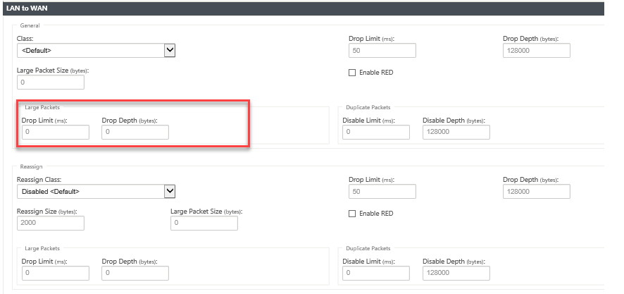
Large Packet Size: Packets smaller than or equal to this size are assigned the Drop Limit and Drop Depth values specified in the fields to the right of the Class field.
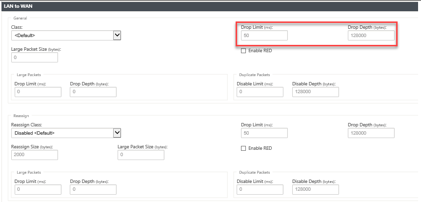
Packets larger than this size are assigned the values specified in the default Drop Limit and Drop Depth fields in the Large Packets section of the screen.
-
Drop Limit: Length of time after which packets waiting in the class scheduler are dropped. Not applicable for a bulk class.
-
Drop Depth: Queue depth threshold after which packets are dropped.
-
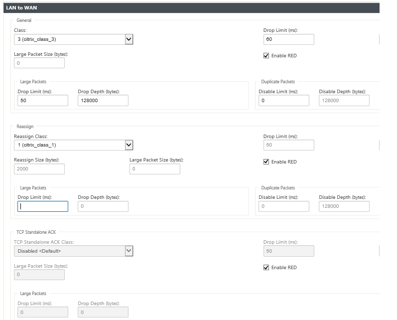
Enable RED: Random Early Detection (RED) ensures fair sharing of class resources by discarding packets when congestion occurs.
-
Reassign Size: Packet length that, when exceeded, causes the packet to be reassigned to the class specified in the Reassign Class field.
-
Reassign Class: Class used when the packet length exceeds the packet length specified in the Reassign Size field.
-
Disable Limit: Time for which duplication can be disabled to prevent duplicate packets from consuming bandwidth.
-
Disable Depth: The queue depth of the class scheduler, at which point the duplicate packets will not be generated.
-
TCP Standalone ACK class: High priority class to which TCP standalone acknowledgments are mapped during large file transfers.
-
-
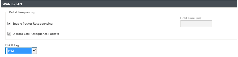
Click the WAN to LAN tile to configure WAN to LAN behavior for this rule.
-
Enable Packets Resequencing: Sequences the packets into the correct order at the destination.
-
Hold Time: Time interval for which the packets are held for resequencing, after which the packets are sent to the LAN.
-
Discard Late Resequencing Packets: Discard out-of-order packets that arrived after the packets needed for resequencing have been sent to the LAN.
-
DSCP Tag: DSCP tag applied to the packets that match this rule, before sending them to the LAN.
-
-
Click Deep Packet Inspection tile and select Enable Passive FTP Detection to allow the rule to detect the port used for FTP data transfer and automatically apply the rule settings to the detected port.
-
Click Apply.
Note
Save the configuration, export it to the change management inbox, and initiate the change management process.
Verify rules
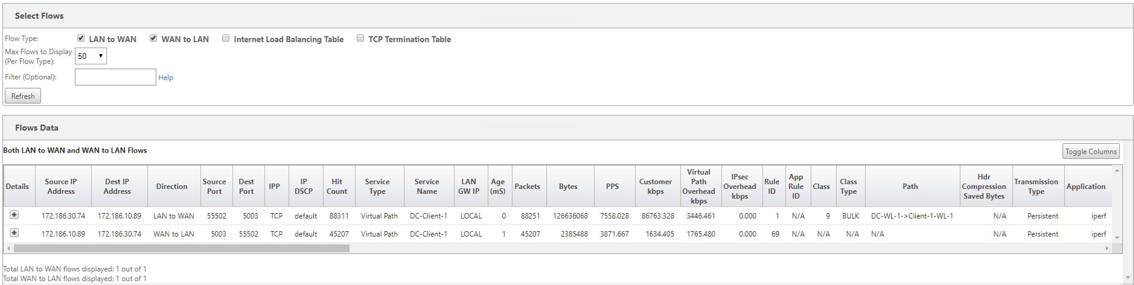
In the Configuration Editor, navigate to Monitoring > Flows. Select Flow Type field located in the Select Flows section at the top of the Flows page. Next to the Flow Type field there is a row of check boxes for selecting the flow information you want to view. Verify if the flow information is according to the configured rules.
Example: The rule “If source IP address is 172.186.30.74 and destination IP address is 172.186.10.89, set Transmit mode as Persistent Path” shows the following Flows Data.
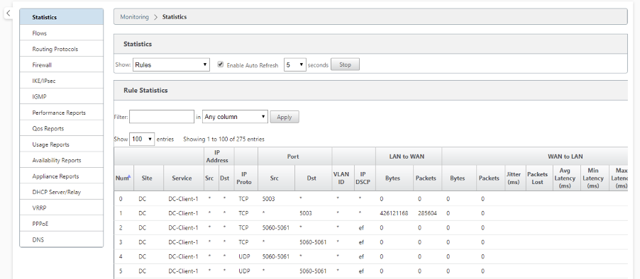
In the Configuration Editor, navigate to Monitoring > Statistics and verify the configured rules.
Share
Share
In this article
This Preview product documentation is Cloud Software Group Confidential.
You agree to hold this documentation confidential pursuant to the terms of your Cloud Software Group Beta/Tech Preview Agreement.
The development, release and timing of any features or functionality described in the Preview documentation remains at our sole discretion and are subject to change without notice or consultation.
The documentation is for informational purposes only and is not a commitment, promise or legal obligation to deliver any material, code or functionality and should not be relied upon in making Cloud Software Group product purchase decisions.
If you do not agree, select I DO NOT AGREE to exit.