-
Configuration guide for Citrix Virtual Apps and Desktops workloads
-
Citrix SD-WAN Orchestrator on-premises configuration on Citrix SD-WAN appliance
-
-
This content has been machine translated dynamically.
Dieser Inhalt ist eine maschinelle Übersetzung, die dynamisch erstellt wurde. (Haftungsausschluss)
Cet article a été traduit automatiquement de manière dynamique. (Clause de non responsabilité)
Este artículo lo ha traducido una máquina de forma dinámica. (Aviso legal)
此内容已经过机器动态翻译。 放弃
このコンテンツは動的に機械翻訳されています。免責事項
이 콘텐츠는 동적으로 기계 번역되었습니다. 책임 부인
Este texto foi traduzido automaticamente. (Aviso legal)
Questo contenuto è stato tradotto dinamicamente con traduzione automatica.(Esclusione di responsabilità))
This article has been machine translated.
Dieser Artikel wurde maschinell übersetzt. (Haftungsausschluss)
Ce article a été traduit automatiquement. (Clause de non responsabilité)
Este artículo ha sido traducido automáticamente. (Aviso legal)
この記事は機械翻訳されています.免責事項
이 기사는 기계 번역되었습니다.책임 부인
Este artigo foi traduzido automaticamente.(Aviso legal)
这篇文章已经过机器翻译.放弃
Questo articolo è stato tradotto automaticamente.(Esclusione di responsabilità))
Translation failed!
Policies
Policies provide the ability to allow, deny, reject, or count and continue specific traffic flows. Applying these policies individually to each site would be difficult as the SD-WAN networks grows. To resolve this issue, groups of firewall filters can be created with a Firewall Policy Template. A Firewall Policy Template can be applied to all sites in the network or only to specific sites. These policies are ordered as either Pre-Appliance Template Policies or Post- Appliance Template Policies. Both network-wide Pre-Appliance and Post-Appliance Template Policies are configured at the Global level. Local policies are configured at the site level under Connections and apply only to that specific site.
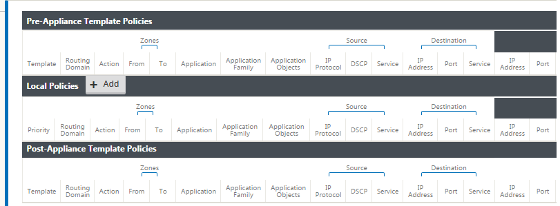
Pre-Appliance Template Policies are applied before any local site policies. Local site policies are applied next, followed by Post-Appliance Template Policies. The goal is to simplify the configuration process by allowing you to apply global policies while still maintaining the flexibility to apply site-specific policies.
Filter policy evaluation order
-
Pre-Templates – compiled policies from all template “PRE” sections.
-
Pre-Global – compiled policies from Global “PRE” section.
-
Local – appliance-level policies.
-
Local Auto Generated – automatically local generated policies.
-
Post-Templates – compiled policies from all template “POST” sections.
-
Post-Global – compiled policies from Global “POST” section.
Policy definitions - Global and Local (site)
You can configure Pre-Appliance and Post-Appliance Template Policies at a global level. Local policies are applied at the site level of an appliance.
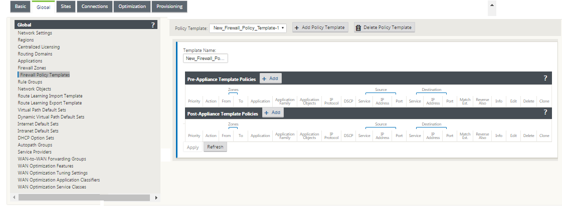
The above screenshot shows the policy template that would apply to the SD-WAN network globally. To apply a template to all sites in the network, navigate to Global > Network Settings > Global Policy Template, and select a specific policy. At the site level, you can add more policy templates, as well as create site specific policies.
The specific configurable attributes for a policy are displayed in the below screen shot, these are the same for all the policies.
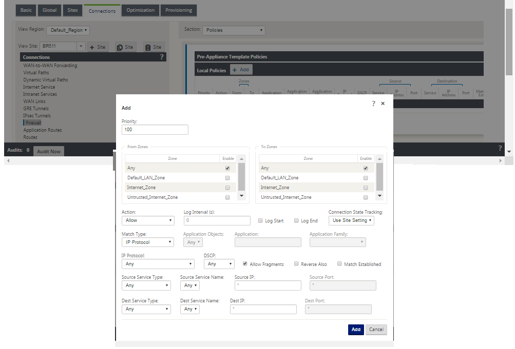
Policy attributes
-
Priority – order in which the policy will be applied within all the defined policies. Lower priority policies are applied before higher priority polices.
-
Zone – flows have a source zone and destination zone.
- From Zone – source zone for the policy.
- To Zone – destination zone for the policy.
-
Action – action to perform on a matched flow.
-
Allow – permit the flow through the Firewall.
-
Drop – deny the flow through the firewall by dropping the packets.
-
Reject – deny the flow through the firewall and send a protocol specific response. TCP will send a reset, ICMP will send an error message.
-
Count and Continue – count the number of packets and bytes for this flow, then continue down the policy list.
-
-
Log Interval – time in seconds between logging the number of packets matching the policy to the firewall log file or the syslog server, if it is configured.
-
Log Start – if selected, a log entry is created for the new flow.
-
Log End – log the data for a flow when the flow is deleted.
-
Note
The default Log Interval value of 0 means no logging.
-
Track – allows the firewall to track the state of a flow and display this information in the Monitoring > Firewall > Connections table. If the flow is not tracked, the state will show NOT_TRACKED. See the table for the state tracking based on protocol below. Use the setting defined at the site level under Firewall > Settings > Advanced > Default Tracking.
-
No Track – flow state is not enabled.
-
Track – displays the current state of the flow (which matched this policy).
-
-
Match Type – select one of the following match types
-
IP Protocol – If this match type is selected, select an IP protocol that the filter will match with. Options include ANY, TCP, UDP ICMP and so
-
Application – If this match type is selected, specify the application that is used as a match criteria for this filter.
-
Application Family – If this match type is selected, select an application family that is used as a match criteria for this filter.
-
Application Object – If this match type is selected, select an application family that is used as a match criteria for this filter.
-
For more information on application, application family and application object, see Application Classification.
-
DSCP – allow the user to match on a DSCP tag setting.
-
Allow Fragments – allow IP fragments that match this filter policy.
Note
The firewall does not reassemble fragmented frames.
-
Reverse Also – automatically add a copy of this filter policy with source and destination settings reversed.
-
Match Established – match incoming packets for a connection to which outgoing packets were allowed.
-
Source Service Type – in reference to a SD-WAN service – Local (to the appliance), Virtual Path, Intranet, IPhost, or Internet are examples of Service Types.
-
IPhost Option - This is a new service type for the Firewall and is used for packets that are generated by the SD-WAN application. For example, running a ping from the Web UI of the SD-WAN results in a packet sourced from a SD-WAN Virtual IP address. Creating a policy for this IP address would require the user to select the IPhost option.
-
Source Service Name – name of a service tied to the service type. For example, if virtual path is selected for Source Service type, this would be the name of the specific virtual path. This is not always required and depends on the service type selected.
-
Source IP address – typical IP address and subnet mask the filter will use to match.
-
Source Port – source port the specific application will use.
-
Destination Service Type - in reference to a SD-WAN service – Local (to the appliance), Virtual Path, Intranet, IPhost, or Internet are examples of service types.
-
Destination Service Name - name of a service tied to the service type. This is not always required and depends on the service type selected.
-
Destination IP Address - typical IP address and subnet mask the filter will use to match.
-
Destination Port – destination port the specific application will use (i.e. HTTP destination port 80 for the TCP protocol).
The track option provides much more detail about a flow. The state information tracked in the state tables is included below.
State table for the track option
There are only a few states that are consistent:
-
INIT- connection created, but the initial packet was invalid.
-
O_DENIED- packets that created the connection are denied by a filter policy.
-
R_DENIED- packets from the responder are denied by a filter policy.
-
NOT_TRACKED- the connection is not statefully tracked but is otherwise allowed.
-
CLOSED- the connection has timed out or otherwise been closed by the protocol.
-
DELETED- the connection is in the process of being removed. The DELETED state will almost never be seen.
All other states are protocol specific and require stateful tracking be enabled.
TCP can report the following states:
-
SYN_SENT - first TCP SYN message seen.
-
SYN_SENT2 - SYN message seen in both directions, no SYN+ACK (AKA simultaneous open).
-
SYN_ACK_RCVD - SYN+ACK received.
-
ESTABLISHED- second ACK received, connection is fully established.
-
FIN_WAIT - first FIN message seen.
-
CLOSE_WAIT - FIN message seen in both directions.
-
TIME_WAIT - last ACK seen in both directions. Connection is now closed waiting for reopen.
All other IP protocols (notably ICMP and UDP) have the following states:
-
NEW - packets seen in one direction.
-
ESTABLISHED - packets seen in both directions.
Share
Share
This Preview product documentation is Cloud Software Group Confidential.
You agree to hold this documentation confidential pursuant to the terms of your Cloud Software Group Beta/Tech Preview Agreement.
The development, release and timing of any features or functionality described in the Preview documentation remains at our sole discretion and are subject to change without notice or consultation.
The documentation is for informational purposes only and is not a commitment, promise or legal obligation to deliver any material, code or functionality and should not be relied upon in making Cloud Software Group product purchase decisions.
If you do not agree, select I DO NOT AGREE to exit.