-
-
-
クライアント、サーバー、およびバックプレーンの共通スイッチ
This content has been machine translated dynamically.
Dieser Inhalt ist eine maschinelle Übersetzung, die dynamisch erstellt wurde. (Haftungsausschluss)
Cet article a été traduit automatiquement de manière dynamique. (Clause de non responsabilité)
Este artículo lo ha traducido una máquina de forma dinámica. (Aviso legal)
此内容已经过机器动态翻译。 放弃
このコンテンツは動的に機械翻訳されています。免責事項
이 콘텐츠는 동적으로 기계 번역되었습니다. 책임 부인
Este texto foi traduzido automaticamente. (Aviso legal)
Questo contenuto è stato tradotto dinamicamente con traduzione automatica.(Esclusione di responsabilità))
This article has been machine translated.
Dieser Artikel wurde maschinell übersetzt. (Haftungsausschluss)
Ce article a été traduit automatiquement. (Clause de non responsabilité)
Este artículo ha sido traducido automáticamente. (Aviso legal)
この記事は機械翻訳されています.免責事項
이 기사는 기계 번역되었습니다.책임 부인
Este artigo foi traduzido automaticamente.(Aviso legal)
这篇文章已经过机器翻译.放弃
Questo articolo è stato tradotto automaticamente.(Esclusione di responsabilità))
Translation failed!
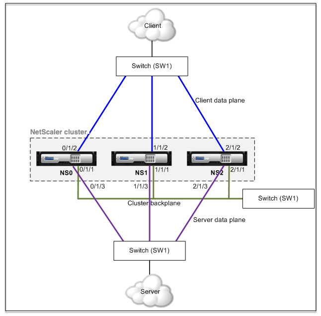
クライアント、サーバー、およびバックプレーンの共通スイッチ
この展開では、クライアント、サーバー、バックプレーンは同じスイッチ上の専用インターフェイスを使用してNetScalerクラスターと通信します。
-
NS0-ノード ID: 0、NSIP: 10.102.29.60
-
NS1-ノード ID: 1、NSIP: 10.102.29.70
-
NS2-ノード ID: 2、NSIP: 10.102.29.80
クライアント、サーバ、およびバックプレーン用の共通スイッチを使用してクラスタを展開するには
-
NS0、NS1、NS2 のノードのクラスタを作成します。
-
クラスタに追加する最初のノードにログオンし、次の操作を行います。
> create cluster instance 1 > add cluster node 0 10.102.29.60 -state ACTIVE -backplane 0/1/1 > enable cluster instance 1 > add ns ip 10.102.29.61 255.255.255.255 -type CLIP > save ns config > reboot -warm -
クラスタの IP アドレスにログオンし、次の操作を行います。
> add cluster node 1 10.102.29.70 -state ACTIVE -backplane 1/1/1 > add cluster node 2 10.102.29.80 -state ACTIVE -backplane 2/1/1 -
ノード 10.102.29.70 および 10.102.29.80 にログオンし、ノードをクラスタに参加させます。
> join cluster -clip 10.102.29.61 -password nsroot
> save ns config
> reboot -warm
前のコマンドに見られるように、インターフェース 0/1/1, 1/1/1, そして 2/1/1 3つのクラスターノードのバックプレーンインターフェイスとして構成されます。
-
-
クラスタ IP アドレスに、バックプレーン、クライアント、およびサーバインターフェイスの VLAN を作成します。
//バックプレーンインタフェースの場合
> add vlan 10
> bind vlan 10 0/1/1 1/1/1 2/1/1
//クライアント側インタフェースの場合
> add vlan 20
> bind vlan 20 0/1/2 1/1/2 2/1/2
//サーバー側インタフェースの場合
> add vlan 30 > bind vlan 30 0/1/3 1/1/3 2/1/3 -
スイッチ上で、バックプレーンインターフェイス、およびクライアントおよびサーバインターフェイスに対応するインターフェイスの VLAN を作成します。Cisco® Nexus 7000 C7010 リリース 5.2 (1) スイッチの設定例を以下に示します。他のスイッチでも同様の設定を行う必要があります。</span>
//バックプレーンインターフェース用。Repeat for each interface…
> interface Ethernet2/47
  switchport access vlan 100
  switchport mode access
  end
//クライアントインターフェース用。Repeat for each interface…
> interface Ethernet2/48
  switchport access vlan 200
  switchport mode access
  end
//サーバーインターフェース用。Repeat for each interface…
> interface Ethernet2/49
  switchport access vlan 300
  switchport mode access
  end
共有
共有
この記事の概要
This Preview product documentation is Cloud Software Group Confidential.
You agree to hold this documentation confidential pursuant to the terms of your Cloud Software Group Beta/Tech Preview Agreement.
The development, release and timing of any features or functionality described in the Preview documentation remains at our sole discretion and are subject to change without notice or consultation.
The documentation is for informational purposes only and is not a commitment, promise or legal obligation to deliver any material, code or functionality and should not be relied upon in making Cloud Software Group product purchase decisions.
If you do not agree, select I DO NOT AGREE to exit.