-
Getting Started with NetScaler
-
Deploy a NetScaler VPX instance
-
Optimize NetScaler VPX performance on VMware ESX, Linux KVM, and Citrix Hypervisors
-
Apply NetScaler VPX configurations at the first boot of the NetScaler appliance in cloud
-
Configure simultaneous multithreading for NetScaler VPX on public clouds
-
Install a NetScaler VPX instance on Microsoft Hyper-V servers
-
Install a NetScaler VPX instance on Linux-KVM platform
-
Prerequisites for installing NetScaler VPX virtual appliances on Linux-KVM platform
-
Provisioning the NetScaler virtual appliance by using OpenStack
-
Provisioning the NetScaler virtual appliance by using the Virtual Machine Manager
-
Configuring NetScaler virtual appliances to use SR-IOV network interface
-
Configure a NetScaler VPX on KVM hypervisor to use Intel QAT for SSL acceleration in SR-IOV mode
-
Configuring NetScaler virtual appliances to use PCI Passthrough network interface
-
Provisioning the NetScaler virtual appliance by using the virsh Program
-
Provisioning the NetScaler virtual appliance with SR-IOV on OpenStack
-
Configuring a NetScaler VPX instance on KVM to use OVS DPDK-Based host interfaces
-
-
Deploy a NetScaler VPX instance on AWS
-
Deploy a VPX high-availability pair with elastic IP addresses across different AWS zones
-
Deploy a VPX high-availability pair with private IP addresses across different AWS zones
-
Protect AWS API Gateway using the NetScaler Web Application Firewall
-
Deploy NetScaler GSLB on AWS
-
Configure a NetScaler VPX instance to use SR-IOV network interface
-
Configure a NetScaler VPX instance to use Enhanced Networking with AWS ENA
-
Deploy a NetScaler VPX instance on Microsoft Azure
-
Network architecture for NetScaler VPX instances on Microsoft Azure
-
Configure multiple IP addresses for a NetScaler VPX standalone instance
-
Configure a high-availability setup with multiple IP addresses and NICs
-
Configure a high-availability setup with multiple IP addresses and NICs by using PowerShell commands
-
Deploy a NetScaler high-availability pair on Azure with ALB in the floating IP-disabled mode
-
Configure a NetScaler VPX instance to use Azure accelerated networking
-
Configure HA-INC nodes by using the NetScaler high availability template with Azure ILB
-
Configure a high-availability setup with Azure external and internal load balancers simultaneously
-
Configure a NetScaler VPX standalone instance on Azure VMware solution
-
Configure a NetScaler VPX high availability setup on Azure VMware solution
-
Configure address pools (IIP) for a NetScaler Gateway appliance
-
Deploy a NetScaler VPX instance on Google Cloud Platform
-
Deploy a VPX high-availability pair on Google Cloud Platform
-
Deploy a VPX high-availability pair with external static IP address on Google Cloud Platform
-
Deploy a single NIC VPX high-availability pair with private IP address on Google Cloud Platform
-
Deploy a VPX high-availability pair with private IP addresses on Google Cloud Platform
-
Install a NetScaler VPX instance on Google Cloud VMware Engine
-
-
Solutions for Telecom Service Providers
-
Load Balance Control-Plane Traffic that is based on Diameter, SIP, and SMPP Protocols
-
Provide Subscriber Load Distribution Using GSLB Across Core-Networks of a Telecom Service Provider
-
Authentication, authorization, and auditing application traffic
-
Basic components of authentication, authorization, and auditing configuration
-
Web Application Firewall protection for VPN virtual servers and authentication virtual servers
-
On-premises NetScaler Gateway as an identity provider to Citrix Cloud
-
Authentication, authorization, and auditing configuration for commonly used protocols
-
Troubleshoot authentication and authorization related issues
-
-
-
-
-
-
Configure DNS resource records
-
Configure NetScaler as a non-validating security aware stub-resolver
-
Jumbo frames support for DNS to handle responses of large sizes
-
Caching of EDNS0 client subnet data when the NetScaler appliance is in proxy mode
-
Use case - configure the automatic DNSSEC key management feature
-
Use Case - configure the automatic DNSSEC key management on GSLB deployment
-
-
-
Persistence and persistent connections
-
Advanced load balancing settings
-
Gradually stepping up the load on a new service with virtual server–level slow start
-
Protect applications on protected servers against traffic surges
-
Retrieve location details from user IP address using geolocation database
-
Use source IP address of the client when connecting to the server
-
Use client source IP address for backend communication in a v4-v6 load balancing configuration
-
Set a limit on number of requests per connection to the server
-
Configure automatic state transition based on percentage health of bound services
-
-
Use case 2: Configure rule based persistence based on a name-value pair in a TCP byte stream
-
Use case 3: Configure load balancing in direct server return mode
-
Use case 6: Configure load balancing in DSR mode for IPv6 networks by using the TOS field
-
Use case 7: Configure load balancing in DSR mode by using IP Over IP
-
Use case 10: Load balancing of intrusion detection system servers
-
Use case 11: Isolating network traffic using listen policies
-
Use case 12: Configure Citrix Virtual Desktops for load balancing
-
Use case 13: Configure Citrix Virtual Apps and Desktops for load balancing
-
Use case 14: ShareFile wizard for load balancing Citrix ShareFile
-
Use case 15: Configure layer 4 load balancing on the NetScaler appliance
-
-
-
-
Authentication and authorization for System Users
-
-
Configuring a CloudBridge Connector Tunnel between two Datacenters
-
Configuring CloudBridge Connector between Datacenter and AWS Cloud
-
Configuring a CloudBridge Connector Tunnel Between a Datacenter and Azure Cloud
-
Configuring CloudBridge Connector Tunnel between Datacenter and SoftLayer Enterprise Cloud
-
Configuring a CloudBridge Connector Tunnel Between a NetScaler Appliance and Cisco IOS Device
-
CloudBridge Connector Tunnel Diagnostics and Troubleshooting
This content has been machine translated dynamically.
Dieser Inhalt ist eine maschinelle Übersetzung, die dynamisch erstellt wurde. (Haftungsausschluss)
Cet article a été traduit automatiquement de manière dynamique. (Clause de non responsabilité)
Este artículo lo ha traducido una máquina de forma dinámica. (Aviso legal)
此内容已经过机器动态翻译。 放弃
このコンテンツは動的に機械翻訳されています。免責事項
이 콘텐츠는 동적으로 기계 번역되었습니다. 책임 부인
Este texto foi traduzido automaticamente. (Aviso legal)
Questo contenuto è stato tradotto dinamicamente con traduzione automatica.(Esclusione di responsabilità))
This article has been machine translated.
Dieser Artikel wurde maschinell übersetzt. (Haftungsausschluss)
Ce article a été traduit automatiquement. (Clause de non responsabilité)
Este artículo ha sido traducido automáticamente. (Aviso legal)
この記事は機械翻訳されています.免責事項
이 기사는 기계 번역되었습니다.책임 부인
Este artigo foi traduzido automaticamente.(Aviso legal)
这篇文章已经过机器翻译.放弃
Questo articolo è stato tradotto automaticamente.(Esclusione di responsabilità))
Translation failed!
Deploy NetScaler GSLB on AWS
Setting up GSLB for NetScaler on AWS basically consists of configuring NetScaler to load balance traffic to servers located outside the VPC that NetScaler belongs to, such as within another VPC in a different Availability Region or an on-premises data center.
DBS overview
NetScaler GSLB support using DBS (Domain Based Services) for Cloud load balancers allows for the automatic discovery of dynamic cloud services using a cloud load balancer solution. This configuration allows NetScaler to implement Global Server Load Balancing Domain-Name Based Services (GSLB DBS) in an Active-Active environment. DBS allows the scaling of back-end resources in AWS environments from DNS discovery.
This section covers integrations between NetScaler in AWS AutoScaling environments. The final section of the document details the ability to set up a HA pair of NetScaler ADCs that span two different Availability Zones (AZs) specific to an AWS region.
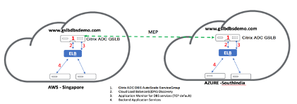
Domain-name based services (DBS) with ELB
GSLB DBS utilizes the FQDN of the user Elastic Load Balancer (ELB) to dynamically update the GSLB Service Groups to include the back-end servers that are being created and deleted within AWS. The back-end servers or instances in AWS can be configured to scale based on network demand or CPU utilization. To configure this feature, point NetScaler to the ELB to dynamically route to different servers in AWS without having to manually update NetScaler every time an instance is created and deleted within AWS. NetScaler DBS feature for GSLB Service Groups uses DNS aware service discovery to determine the member service resources of the DBS namespace identified in the AutoScale group.
NetScaler GSLB DBS autoScale components with Cloud Load Balancers:
Configure AWS components
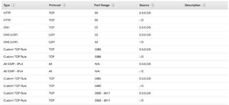
Security groups
Note:
We recommend you to create different security groups for ELB, NetScaler GSLB Instance, and Linux instance, as the set of rules required for each of these entities is different. This example has a consolidated Security Group configuration for brevity.
To ensure the proper configuration of the virtual firewall, see: Security Groups for Your VPC.
- Log in to the user AWS resource group and navigate to EC2 > NETWORK & SECURITY > Security Groups.
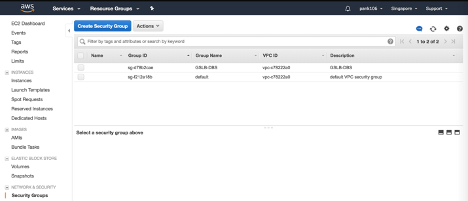
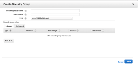
- Click Create Security Group and provide a name and description. This security group encompasses NetScaler and Linux back-end web servers.
-
Add the inbound port rules from the following screenshot.
Note:
Limiting Source IP access is recommended for granular hardening. For more information, see: Web Server Rules.
-
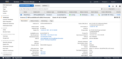
Amazon Linux Back-end Web Services
- Log in to the user AWS resource group and navigate to EC2 > Instances.

- Click Launch Instance using the details that follow to configure the Amazon Linux instance.
Enter the details about setting up a Web Server or back-end service on this instance.

-
NetScaler Configuration
- Log in to the user AWS resource group and navigate to EC2 > Instances.
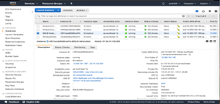
- Click Launch Instance and use the following details to configure the Amazon AMI instance.
-
Elastic IP Configuration
Note:
NetScaler can also be made to run with a single elastic IP if necessary to reduce cost, by not having a public IP for the NSIP. Instead, attach an elastic IP to the SNIP which can cover for management access to the box, in addition to the GSLB site IP and ADNS IP.
-
Log in to the user AWS resource group and navigate to EC2 > NETWORK & SECURITY > Elastic IPs.
-
Click Allocate new address to create a Elastic IP address.
-
Configure the Elastic IP to point to the user running NetScaler instance within AWS.
-
Configure a second Elastic IP and again point it to the user running NetScaler instance.
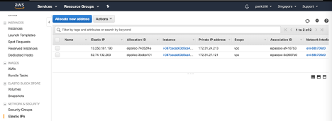
-
-
Elastic Load Balancer
- Log in to the user AWS resource group and navigate to EC2 > LOAD BALANCING > Load Balancers.
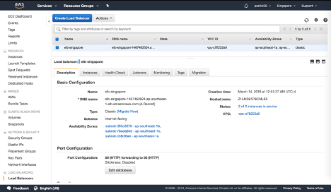
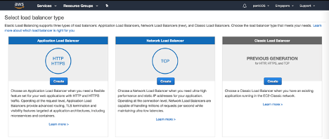
- Click Create Load Balancer to configure a classic load balancer.
The user Elastic Load Balancers allow users to load balance their back-end Amazon Linux instances while also being able to Load Balance other instances that are spun up based on demand.
Configuring global server load balancing domain-name based services
For Traffic Management Configurations, see Configure NetScaler GSLB domain-based service.
Deployment types
Three-NIC Deployment
-
Typical Deployments
-
GSLB StyleBook
-
With ADM
-
With GSLB (Route53 w/domain registration)
-
Licensing - Pooled/Marketplace
-
-
Use Cases
-
Three-NIC Deployments are used to achieve real isolation of data and management traffic.
-
Three-NIC Deployments also improve the scale and performance of the ADC.
-
Three-NIC Deployments are used in network applications where throughput is typically 1 Gbps or higher and a Three-NIC Deployment is recommended.
-
CFT deployment
Customers would deploy using CloudFormation Templates if they are customizing their deployments or they are automating their deployments.
Deployment steps
The folloiwng are the deployments steps:
- Three-NIC deployment for GSLB
- Licensing
- Deployment options
Three-NIC deployment for GSLB
NetScaler VPX instance is available as an Amazon Machine Image (AMI) in the AWS marketplace, and it can be launched as an Elastic Compute Cloud (EC2) instance within an AWS VPC. The minimum EC2 instance type allowed as a supported AMI on NetScaler VPX is m4.large. NetScaler VPX AMI instance requires a minimum of 2 virtual CPUs and 2 GB of memory. An EC2 instance launched within an AWS VPC can also provide the multiple interfaces, multiple IP addresses per interface, and public and private IP addresses needed for VPX configuration. Each VPX instance requires at least three IP subnets:
- A management subnet
- A client-facing subnet (VIP)
- A back-end facing subnet (SNIP)
NetScaler recommends three network interfaces for a standard VPX instance on AWS installation.
AWS currently makes multi-IP functionality available only to instances running within an AWS VPC. A VPX instance in a VPC can be used to load balance servers running in EC2 instances. An Amazon VPC allows users to create and control a virtual networking environment, including their own IP address range, subnets, route tables, and network gateways.
Note:
By default, users can create up to 5 VPC instances per AWS region for each AWS account. Users can request higher VPC limits by submitting Amazon’s request form here: Amazon VPC Request.
Licensing
A NetScaler VPX instance on AWS requires a license. The following licensing options are available for NetScaler VPX instances running on AWS:
- Free (unlimited)
- Hourly
- Annual
Bring your own license
Free Trial (all NetScaler VPX-AWS subscription offerings for 21 days free in AWS marketplace).
Deployment options
Users can deploy a NetScaler VPX standalone instance on AWS. For more information, see Deploy a NetScaler VPX standalone instance on AWS
NetScaler global load balancing for hybrid and multi-cloud dployments
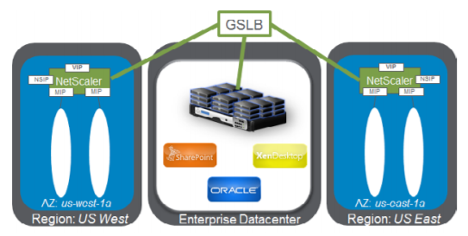
NetScaler hybrid and multi-cloud global server load balancing (GSLB) solution enables users to distribute application traffic across multiple data centers in hybrid clouds, multiple clouds, and on-premises deployments. NetScaler hybrid and multi-cloud GSLB solution helps users to manage their load balancing setup in hybrid or multi-cloud environments without altering the existing setup. Also, if users have an on-premises setup, they can test some of their services in the cloud by using NetScaler hybrid and multi-cloud GSLB solution before completely migrating to the cloud. For example, users can route only a small percentage of their traffic to the cloud, and handle most of the traffic on-premises. NetScaler hybrid and multi-cloud GSLB solution also enables users to manage and monitor NetScaler instances across geographic locations from a single, unified console.
A hybrid and multi-cloud architecture can also improve overall enterprise performance by avoiding “vendor lock-in” and using different infrastructure to meet the needs of user partners and customers. With multiple cloud architecture, users can manage their infrastructure costs better as they now have to pay only for what they use. Users can also scale their applications better as they now use the infrastructure on demand. It also provides the ability to quickly switch from one cloud to another to take advantage of the best offerings of each provider.
Architecture of NetScaler hybrid and multi-cloud GSLB Solution
The following diagram illustrates the architecture of NetScaler hybrid and multi-cloud GSLB feature.
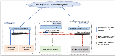
NetScaler GSLB nodes handle the DNS name resolution. Any of these GSLB nodes can receive DNS requests from any client location. The GSLB node that receives the DNS request returns the load balancer virtual server IP address as selected by the configured load balancing method. Metrics (site, network, and persistence metrics) are exchanged between the GSLB nodes using the metrics exchange protocol (MEP), which is a proprietary NetScaler protocol. For more information on the MEP protocol, see: Configure Metrics Exchange Protocol.
The monitor configured in the GSLB node monitors the health status of the load balancing virtual server in the same data center. In a parent-child topology, metrics between the GSLB and NetScaler nodes are exchanged by using MEP. However, configuring monitor probes between a GSLB and NetScaler LB node is optional in a parent-child topology.
The NetScaler agent enables communication between the NetScaler Console and the managed instances in the user data center. For more information on NetScaler agents and how to install them, see: Getting Started.
Note:
This document makes the following assumptions:
If users have an existing load balancing setup, it is up and running.
A SNIP address or a GSLB site IP address is configured on each of NetScaler GSLB nodes. This IP address is used as the data center source IP address when exchanging metrics with other data centers.
An ADNS or ADNS-TCP service is configured on each of NetScaler GSLB instances to receive the DNS traffic.
The required firewall and security groups are configured in the cloud service providers.
Security groups configuration
Users must set up the required firewall/security groups configuration in the cloud service providers. For more information about AWS security features, see: AWS/Documentation/Amazon VPC/User Guide/Security.
Also, on the GSLB node, users must open port 53 for ADNS service/DNS server IP address and port 3009 for GSLB site IP address for MEP traffic exchange. On the load balancing node, users must open the appropriate ports to receive the application traffic. For example, users must open port 80 for receiving HTTP traffic and open port 443 for receiving HTTPS traffic. Open port 443 for NITRO communication between the NetScaler agent and NetScaler Console.
For the dynamic round trip time GSLB method, users must open port 53 to allow UDP and TCP probes depending on the configured LDNS probe type. The UDP or the TCP probes are initiated using one of the SNIPs and therefore this setting must be done for security groups bound to the server-side subnet.
Capabilities of NetScaler hybrid and multi-cloud GSLB solution
Some of the capabilities of NetScaler hybrid and multi-cloud GSLB solution are described in this section.
Compatibility with other load balancing solutions
NetScaler hybrid and multi-cloud GSLB solution supports various load balancing solutions such as NetScaler load balancer, NGINX, HAProxy, and other third-party load balancers.
Note:
Load balancing solutions other than NetScaler are supported only if proximity-based and non-metric based GSLB methods are used and if parent-child topology is not configured.
GSLB methods
NetScaler hybrid and multi-cloud GSLB solution supports the following GSLB methods.
-
Metric-based GSLB methods. Metric-based GSLB methods collect metrics from the other NetScaler nodes through the metrics exchange protocol.
-
Least Connection: The client request is routed to the load balancer that has the fewest active connections.
-
Least Bandwidth: The client request is routed to the load balancer that is currently serving the least amount of traffic.
-
Least Packets: The client request is routed to the load balancer that has received the fewest packets in the last 14 seconds.
-
-
Non-metric based GSLB methods
-
Round Robin: The client request is routed to the IP address of the load balancer that is at the top of the list of load balancers. That load balancer then moves to the bottom of the list.
-
Source IP Hash: This method uses the hashed value of the client IP address to select a load balancer.
-
-
Proximity-based GSLB methods
-
Static Proximity: The client request is routed to the load balancer that is closest to the client IP address.
-
Round-Trip Time (RTT): This method uses the RTT value (the time delay in the connection between the client’s local DNS server and the data center) to select the IP address of the best performing load balancer.
-
For more information on the load balancing methods, see: Load Balancing Algorithms.
GSLB topologies
NetScaler hybrid and multi-cloud GSLB solution supports the active-passive topology and parent-child topology.
-
Active-passive topology - Provides disaster recovery and ensures continuous availability of applications by protecting against points of failure. If the primary data center goes down, the passive data center becomes operational. For more information about GSLB active-passive topology, see: Configure GSLB for Disaster Recovery.
-
Parent-child topology – Can be used if customers are using the metric-based GSLB methods to configure GSLB and LB nodes and if the LB nodes are deployed on a different NetScaler instance. In a parent-child topology, the LB node (child site) must be a NetScaler appliance because the exchange of metrics between the parent and child site is through the metrics exchange protocol (MEP).
For more information about parent-child topology, see: Parent-Child Topology Deployment using the MEP Protocol.
IPv6 support
NetScaler hybrid and multi-cloud GSLB solution also supports IPv6.
Monitoring
NetScaler hybrid and multi-cloud GSLB solution supports built-in monitors with an option to enable the secure connection. However, if LB and GSLB configurations are on the same NetScaler instance or if parent-child topology is used, configuring monitors is optional.
Persistence
NetScaler hybrid and multi-cloud GSLB solution supports the following:
-
Source IP based persistence sessions, so that multiple requests from the same client are directed to the same service if they arrive within the configured time-out window. If the time-out value expires before the client sends another request, the session is discarded, and the configured load balancing algorithm is used to select a new server for the client’s next request.
-
Spillover persistence so that the backup virtual server continues to process the requests it receives, even after the load on the primary falls below the threshold. For more information, see: Configure Spillover.
-
Site persistence so that the GSLB node selects a data center to process a client request and forwards the IP address of the selected data center for all subsequent DNS requests. If the configured persistence applies to a site that is DOWN, the GSLB node uses a GSLB method to select a new site, and the new site becomes persistent for subsequent requests from the client.
Configuration by using NetScaler Console styleBooks
Customers can use the default Multi-cloud GSLB StyleBook on NetScaler Console to configure NetScaler instances with hybrid and multi-cloud GSLB configurations.
Customers can use the default Multi-cloud GSLB StyleBook for the LB Node StyleBook to configure NetScaler load balancing nodes which are the child sites in a parent-child topology that handle the application traffic. Use this StyleBook only if users want to configure LB nodes in a parent-child topology. However, each LB node must be configured separately using this StyleBook.
Workflow of NetScaler hybrid and multi-cloud GSLB solution configuration
Customers can use the shipped Multi-cloud GSLB StyleBook on NetScaler Console to configure NetScaler instances with hybrid and multi-cloud GSLB configurations.
The following diagram shows the workflow for configuring a NetScaler hybrid and multi-cloud GSLB solution. The steps in the workflow diagram are explained in more detail after the diagram.
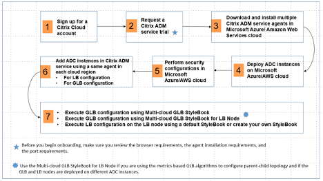
Perform the following tasks as a cloud administrator:
-
Sign up for a NetScaler Cloud account.
To start using NetScaler Console, create a NetScaler Cloud company account or join an existing one that has been created by someone in your company.
-
After users log on to NetScaler Cloud, click Manage on the NetScaler Application Delivery Management tile to set up the ADM service for the first time.
-
Download and install multiple NetScaler Console service agents.
Users must install and configure the NetScaler Console service agent in their network environment to enable communication between the NetScaler Console and the managed instances in their data center or cloud. Install an agent in each region, so that they can configure LB and GSLB configurations on the managed instances. The LB and GSLB configurations can share a single agent. For more information on the above three tasks, see: Getting Started.
-
Deploy load balancers on Microsoft AWS cloud/on-premises data centers.
Depending on the type of load balancers that users are deploying on cloud and on-premises, provision them accordingly. For example, users can provision NetScaler VPX instances in an Amazon Web Services (AWS) virtual private cloud and in on-premises data centers. Configure NetScaler instances to function as LB or GSLB nodes in standalone mode, by creating the virtual machines and configuring other resources. For more information on how to deploy NetScaler VPX instances, see the following documents:
-
Perform security configurations.
Configure network security groups and network ACLs in ARM and in AWS to control inbound and outbound traffic for user instances and subnets.
-
Add NetScaler instances in NetScaler Console.
NetScaler instances are network appliances or virtual appliances that users want to discover, manage, and monitor from NetScaler Console. To manage and monitor these instances, users must add the instances to the service and register both LB (if users are using NetScaler for LB) and GSLB instances. For more information on how to add NetScaler instances in the NetScaler Console, see: Getting Started
-
Implement the GSLB and LB configurations using default NetScaler Console StyleBooks.
-
Use Multi-cloud GSLB StyleBook to execute the GSLB configuration on the selected GSLB NetScaler instances.
-
Implement the load balancing configuration. (Users can skip this step if they already have LB configurations on the managed instances.) Users can configure load balancers on NetScaler instances in one of two ways:
-
Manually configure the instances for load balancing the applications. For more information on how to manually configure the instances, see: Set up Basic Load Balancing.
-
Use StyleBooks. Users can use one of the NetScaler Console StyleBooks (HTTP/SSL Load Balancing StyleBook or HTTP/SSL Load Balancing (with Monitors) StyleBook) to create the load balancer configuration on the selected NetScaler instance. Users can also create their own StyleBooks. For more information on StyleBooks, see: StyleBooks.
-
-
Use Multi-cloud GSLB StyleBook for LB Node to configure GSLB parent-child topology in any of the following cases:
-
If users are using the metric-based GSLB algorithms (Least Packets, Least Connections, Least Bandwidth) to configure GSLB and LB nodes and if the LB nodes are deployed on a different NetScaler instance.
-
If site persistence is required.
-
Using styleBooks to configure GSLB on NetScaler LB nodes
Customers can use the Multi-cloud GSLB StyleBook for LB Node if they are using the metric-based GSLB algorithms (Least Packets, Least Connections, Least Bandwidth) to configure GSLB and LB nodes and if the LB nodes are deployed on a different NetScaler instance.
Users can also use this StyleBook to configure more child sites for an existing parent site. This StyleBook configures one child site at a time. So, create as many configurations (config packs) from this StyleBook as there are child sites. The StyleBook applies the GSLB configuration on the child sites. Users can configure a maximum of 1024 child sites.
Note:
Use Multi-cloud GSLB StyleBook to configure the parent sites.
This StyleBook makes the following assumptions:
-
A SNIP address or a GSLB site IP address is configured.
-
The required firewall and security groups are configured in the cloud service providers.
Configuring a child site in a parent-child topology by using multi-cloud GSLB styleBook for LB node
-
Navigate to Applications > Configuration > Create New.
-
Navigate to Applications > Configuration, and click Create New.
The StyleBook appears as a user interface page on which users can enter the values for all the parameters defined in this StyleBook.
Note:
The terms data center and sites are used interchangeably in this document.
-
Set the following parameters:
-
Application Name. Enter the name of the GSLB application deployed on the GSLB sites for which you want to create child sites.
-
Protocol. Select the application protocol of the deployed application from the drop-down list box.
-
LB Health Check (Optional)
-
Health Check Type. From the drop-down list box, select the type of probe used for checking the health of the load balancer VIP address that represents the application on a site.
-
Secure Mode. (Optional) Select Yes to enable this parameter if SSL based health checks are required.
-
HTTP Request. (Optional) If users selected HTTP as the health-check type, enter the full HTTP request used to probe the VIP address.
-
List of HTTP Status Response Codes. (Optional) If users selected HTTP as the health check type, enter the list of HTTP status codes expected in responses to HTTP requests when the VIP is healthy.
-
-
Configuring parent site.
-
Provide the details of the parent site (GSLB node) under which you want to create the child site (LB node).
-
Site Name. Enter the name of the parent site.
-
Site IP Address. Enter the IP address that the parent site uses as its source IP address when exchanging metrics with other sites. This IP address is assumed to be already configured on the GSLB node in each site.
-
Site Public IP Address. (Optional) Enter the Public IP address of the parent site that is used to exchange metrics, if that site’s IP address is NAT’ed.
-
-
-
Configuring child site.
-
Provide the details of the child site.
-
Site name. Enter the name of the site.
-
Site IP Address. Enter the IP address of the child site. Here, use the private IP address or SNIP of NetScaler node that is being configured as a child site.
-
Site Public IP Address. (Optional) Enter the Public IP address of the child site that is used to exchange metrics, if that site’s IP address is NAT’ed.
-
-
-
Configuring active GSLB services (optional)
-
Configure active GSLB services only if the LB virtual server IP address is not a public IP address. This section allows users to configure the list of local GSLB services on the sites where the application is deployed.
-
Service IP. Enter the IP address of the load balancing virtual server on this site.
-
Service Public IP Address. If the virtual IP address is private and has a public IP address NAT’ed to it, specify the public IP address.
-
Service Port. Enter the port of the GSLB service on this site.
-
Site Name. Enter the name of the site on which the GSLB service is located.
-
-
-
Click Target Instances and select NetScaler instances configured as GSLB instances on each site on which to deploy the GSLB configuration.
-
Click Create to create the LB configuration on the selected NetScaler instance (LB node). Users can also click Dry Run to check the objects that would be created in the target instances. The StyleBook configuration that users have created appears in the list of configurations on the Configurations page. Users can examine, update, or remove this configuration by using the NetScaler Console GUI.
CloudFormation template deployment
NetScaler VPX is available as Amazon Machine Images (AMI) in the AWS Marketplace. Before using a CloudFormation template to provision a NetScaler VPX in AWS, the AWS user has to accept the terms and subscribe to the AWS Marketplace product. Each edition of NetScaler VPX in the Marketplace requires this step.
Each template in the CloudFormation repository has collocated documentation describing the usage and architecture of the template. The templates attempt to codify recommended deployment architecture of NetScaler VPX, or to introduce the user to NetScaler or to demonstrate a particular feature, edition, or option. Users can reuse, modify, or enhance the templates to suit their particular production and testing needs. Most templates require full EC2 permissions in addition to permissions to create IAM roles.
The CloudFormation templates contain AMI Ids that are specific to a particular release of NetScaler VPX (for example, release 12.0-56.20) and edition (for example, NetScaler VPX Platinum Edition - 10 Mbps) OR NetScaler BYOL. To use a different version / edition of NetScaler VPX with a CloudFormation template requires the user to edit the template and replace the AMI IDs.
The latest NetScaler AWS-AMI-IDs are located here: NetScaler AWS CloudFormation Master.
CFT three-NIC deployment
This template deploys a VPC, with 3 subnets (Management, client, server) for 2 Availability Zones. It deploys an Internet Gateway, with a default route on the public subnets. This template also creates a HA pair across Availability Zones with two instances of NetScaler: 3 ENIs associated to 3 VPC subnets (Management, Client, Server) on primary and 3 ENIs associated to 3 VPC subnets (Management, Client, Server) on secondary. All the resource names created by this CFT are prefixed with a tagName of the stack name.
The output of the CloudFormation template includes:
-
PrimaryCitrixADCManagementURL - HTTPS URL to the Management GUI of the Primary VPX (uses self-signed cert)
-
PrimaryCitrixADCManagementURL2 - HTTP URL to the Management GUI of the Primary VPX
-
PrimaryCitrixADCInstanceID - Instance Id of the newly created Primary VPX instance
-
PrimaryCitrixADCPublicVIP - Elastic IP address of the Primary VPX instance associated with the VIP
-
PrimaryCitrixADCPrivateNSIP - Private IP (NS IP) used for management of the Primary VPX
-
PrimaryCitrixADCPublicNSIP - Public IP (NS IP) used for management of the Primary VPX
-
PrimaryCitrixADCPrivateVIP - Private IP address of the Primary VPX instance associated with the VIP
-
PrimaryCitrixADCSNIP - Private IP address of the Primary VPX instance associated with the SNIP
-
SecondaryCitrixADCManagementURL - HTTPS URL to the Management GUI of the Secondary VPX (uses self-signed cert)
-
SecondaryCitrixADCManagementURL2 - HTTP URL to the Management GUI of the Secondary VPX
-
SecondaryCitrixADCInstanceID - Instance Id of the newly created Secondary VPX instance
-
SecondaryCitrixADCPrivateNSIP - Private IP (NS IP) used for management of the Secondary VPX
-
SecondaryCitrixADCPublicNSIP - Public IP (NS IP) used for management of the Secondary VPX
-
SecondaryCitrixADCPrivateVIP - Private IP address of the Secondary VPX instance associated with the VIP
-
SecondaryCitrixADCSNIP - Private IP address of the Secondary VPX instance associated with the SNIP
-
SecurityGroup - Security group id that the VPX belongs to
When providing input to the CFT, the * against any parameter in the CFT implies that it is a mandatory field. For example, VPC ID* is a mandatory field.
The following prerequisites must be met. The CloudFormation template requires sufficient permissions to create IAM roles, beyond normal EC2 full privileges. The user of this template also needs to accept the terms and subscribe to the AWS Marketplace product before using this CloudFormation template.
The following should also be present:
-
Key Pair
-
3 unallocated EIPs
-
Primary Management
-
Client VIP
-
Secondary Management
For more information on provisioning NetScaler VPX instances on AWS, users can visit: Provisioning NetScaler VPX Instances on AWS.
For information on how to configure GSLB using stylebooks visit Using StyleBooks to Configure GSLB
Prerequisites
Before attempting to create a VPX instance in AWS, users should ensure they have the following:
-
An AWS account to launch a NetScaler VPX AMI in an Amazon Web Services (AWS) Virtual Private Cloud (VPC). Users can create an AWS account for free at Amazon.
-
An AWS Identity and Access Management (IAM) user account to securely control access to AWS services and resources for users. For more information about how to create an IAM user account, see the topic: Creating IAM Users (Console).
An IAM role is mandatory for both standalone and high availability deployments. The IAM role must have the following privileges:
- ec2:DescribeInstances
- ec2:DescribeNetworkInterfaces
- ec2:DetachNetworkInterface
- ec2:AttachNetworkInterface
- ec2:StartInstances
- ec2:StopInstances
- ec2:RebootInstances
- ec2:DescribeAddresses
- ec2:AssociateAddress
- ec2:DisassociateAddress
- autoscaling:*
- sns:*
- sqs:*
- iam:SimulatePrincipalPolicy
- iam:GetRole
If the NetScaler CloudFormation template is used, the IAM role is automatically created. The template does not allow selecting an already created IAM role.
Note:
When users log on the VPX instance through the GUI, a prompt to configure the required privileges for IAM role appears. Ignore the prompt if the privileges have already been configured.
- AWS CLI is required to use all the functionality provided by the AWS Management Console from the terminal program. For more information, see: What Is the AWS Command Line Interface?. Users also need the AWS CLI to change the network interface type to SR-IOV.
GSLB prerequisites
The prerequisites for NetScaler GSLB Service Groups include a functioning AWS environment with the knowledge and ability to configure Security Groups, Linux Web Servers, NetScaler ADCs within AWS, Elastic IPs, and Elastic Load Balancers.
GSLB DBS Service integration requires NetScaler version 12.0.57 for AWS ELB load balancer instances.
For latest update about the current supported VPX models and AWS regions, instance types, and services see VPX-AWS support matrix.
Other resources
NetScaler Console GSLB for Hybrid and Multi-Cloud Deployments.
Share
Share
In this article
- DBS overview
- Configure AWS components
- Configuring global server load balancing domain-name based services
- Deployment types
- NetScaler global load balancing for hybrid and multi-cloud dployments
- Architecture of NetScaler hybrid and multi-cloud GSLB Solution
- Capabilities of NetScaler hybrid and multi-cloud GSLB solution
- Configuration by using NetScaler Console styleBooks
- Workflow of NetScaler hybrid and multi-cloud GSLB solution configuration
- CloudFormation template deployment
- Prerequisites
- Other resources
This Preview product documentation is Cloud Software Group Confidential.
You agree to hold this documentation confidential pursuant to the terms of your Cloud Software Group Beta/Tech Preview Agreement.
The development, release and timing of any features or functionality described in the Preview documentation remains at our sole discretion and are subject to change without notice or consultation.
The documentation is for informational purposes only and is not a commitment, promise or legal obligation to deliver any material, code or functionality and should not be relied upon in making Cloud Software Group product purchase decisions.
If you do not agree, select I DO NOT AGREE to exit.