Advanced data center configuration
Secure Private Access hybrid deployment is supported in a multi-data center with multi-sites configuration using NetScaler GSLB in active-active site deployment with site persistency method for GSLB connection proxy.
This topic provides step-by-step instructions for setting up the Secure Private Access hybrid deployment in a multi-data center multi-site configuration.
Prerequisites
Ensure that the following prerequisites are met to deploy Secure Private Access hybrid in multi-data centers.
- NetScaler Gateway version 14.1–66.59 and later.
-
NetScaler GSLB in active-active site deployment. The GSLB domain must be configured on all sites. If you have not yet configured the GSLB, see Active-active site deployment for instructions.
-
Source IP persistence is enabled on GSLB.
- Connection proxy persistence is enabled for CEP session. For details, see Global server load balancing connection proxy.
GSLB configuration CLI commands
We recommend using the NetScaler CLI to configure GSLB. The following are the CLI command templates and an example configuration.
add service <ADNS_SERVICE_NAME> <ADNS_IP> ADNS 53add gslb site <SITE_NAME> <SITE_IP> -sitePassword "<SITE_PASSWORD>"add gslb service <GSLB_SERVICE_NAME> <SERVICE_IP> SSL 443 -publicIP <PUBLIC_IP> -publicPort 443 -siteName <SITE_NAME>add gslb vserver <VSERVER_NAME> SSLbind gslb vserver <VSERVER_NAME> -serviceName <GSLB_SERVICE_NAME>bind gslb vserver <VSERVER_NAME> -domainName <GSLB_DOMAIN_FQDN>set lb vserver <VSERVER_NAME> -PersistenceType SOURCEIPset gslb service <GSLB_SERVICE_NAME> -sitePersistence ConnectionProxybind ssl service <GSLB_SERVICE_NAME> -certKeyName <SERVICE_CERT_KEY>bind ssl vserver <VSERVER_NAME> -certKeyName <CA_CERT_KEY> -CAbind ssl vserver <VSERVER_NAME> -certKeyName <EXTERNAL_CA_CERT_KEY> -CAbind ssl vserver <VSERVER_NAME> -certKeyName <SERVER_CERT_KEY>
References
The following table summarizes the placeholders used in the CLI commands and a brief description of the same.
| Placeholder | Description |
<ADNS_SERVICE_NAME> |
Name of the ADNS service (for example, adns_<env>) |
<ADNS_IP> |
IP address of the ADNS listener on this NetScaler |
<SITE_NAME> |
GSLB site identifier (for example, blue, green) |
<SITE_IP> |
GSLB site IP (SNIP or management IP used for MEP communication) |
<SITE_PASSWORD> |
Shared secret for GSLB site-to-site MEP authentication |
<GSLB_SERVICE_NAME> |
Name of the GSLB service bound to a local/remote load balancing virtual server |
<SERVICE_IP> |
IP address of the backend load balancing virtual server or service |
<PUBLIC_IP> |
Public (NAT) IP address reachable from the internet |
<VSERVER_NAME> |
Name of the GSLB virtual server |
<GSLB_DOMAIN_FQDN> |
FQDN that GSLB resolves for clients |
<SERVICE_CERT_KEY> |
SSL certificate key name bound to the GSLB service |
<CA_CERT_KEY> |
Internal CA certificate key name (bound as -CA) |
<EXTERNAL_CA_CERT_KEY> |
External/public CA certificate key name (bound as -CA) |
<SERVER_CERT_KEY> |
Server certificate key name bound to the virtual server |
Example configuration:
add service adns_staging 10.100.5.50 ADNS 53add gslb site us-east-dc1 10.100.5.60 -sitePassword "password"add gslb service us-east-dc1-svc1 10.100.5.80 SSL 443 -publicIP 203.0.113.42 -publicPort 443 -siteName us-east-dc1add gslb vserver staging_us-east_vs SSLbind gslb vserver staging_us-east_vs -serviceName us-east-dc1-svc1bind gslb vserver staging_us-east_vs -domainName proxy-staging.example.comset lb vserver staging_us-east_vs -PersistenceType SOURCEIPset gslb service us-east-dc1-svc1 -sitePersistence ConnectionProxybind ssl service us-east-dc1-svc1 -certKeyName star_staging_localbind ssl vserver staging_us-east_vs -certKeyName ca_staging.local -CAbind ssl vserver staging_us-east_vs -certKeyName CA.csg.proxy.ext.example -CAbind ssl vserver staging_us-east_vs -certKeyName csg.proxy.ext.example
Data centers setup and configuration
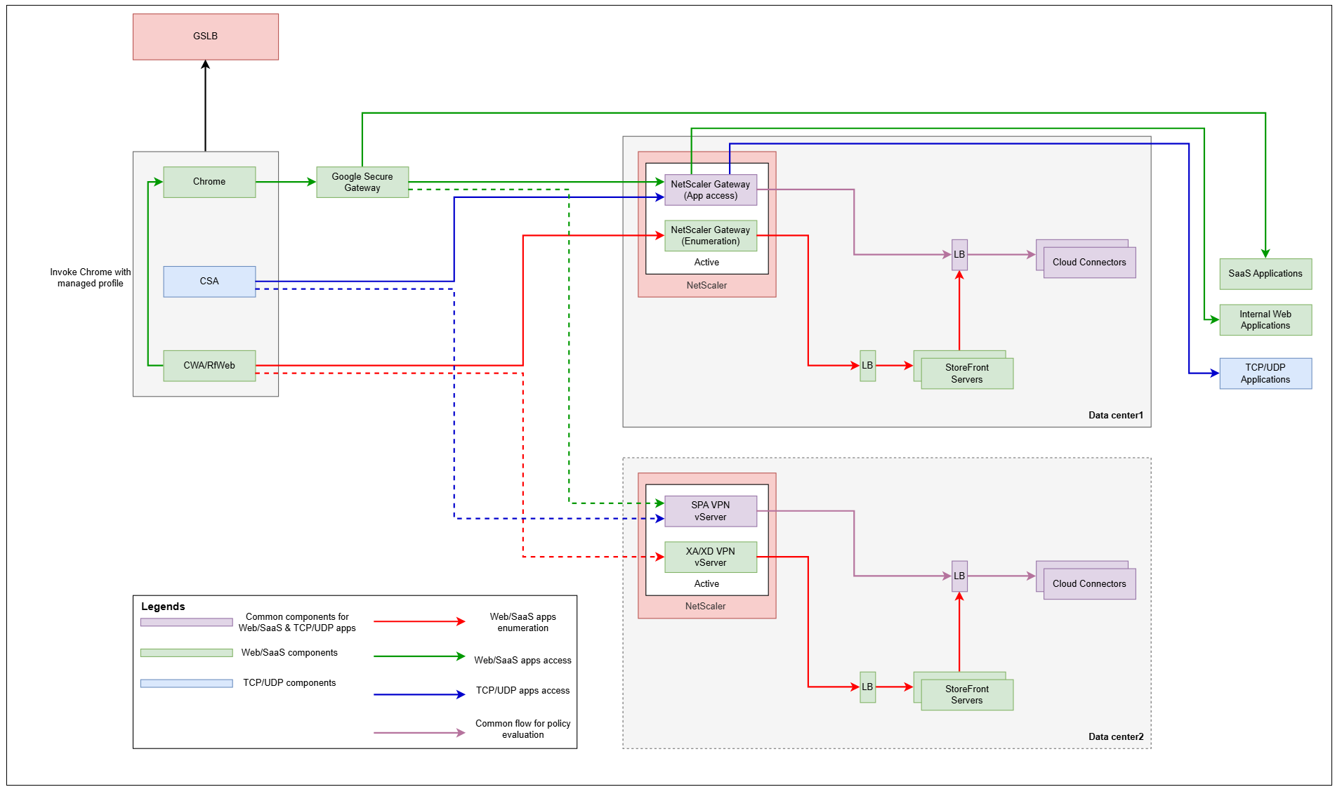
The following figure displays a topology diagram of Secure Private Access hybrid deployment in a multi-data center.

-
Add data centers. For details, see Step 2: Set up the first data center.
-
For each data center, download and run the NetScaler and StoreFront scripts. For details, see Download and run NetScaler and StoreFront scripts.
-
For each data center, upload reports and analyze configurations. For details, see Upload reports and analyze configuration.
-
Review the analysis results.
If all analyzer steps have passed for each data center, you have successfully validated your configuration and can proceed with post-onboarding tasks. For details, see Post-onboarding tasks.