Manage networking
Network configuration procedures in this section differ depending on whether you are configuring a stand-alone host or a host that is part of a resource pool.
Create networks in a standalone host
Because external networks are created for each PIF during host installation, creating extra networks is typically only required to:
-
Use a private network
-
Support advanced operations such as VLANs or NIC bonding
For information about how to add or delete networks using XenCenter, see Add a New Network in the XenCenter documentation.
Open the XenServer host text console.
Create the network by using the network-create command, which returns the UUID of the newly created network:
xe network-create name-label=mynetwork
<!--NeedCopy-->
At this point, the network is not connected to a PIF and therefore is internal.
Create networks in resource pools
All XenServer hosts in a resource pool must have the same number of physical NICs. This requirement is not strictly enforced when a host is joined to a pool. One of the NICs is always designated as the management interface, used for XenServer management traffic.
As all hosts in a pool share a common set of network. It is important to have the same physical networking configuration for XenServer hosts in a pool. PIFs on the individual hosts are connected to pool-wide networks based on device name. For example, all XenServer hosts in a pool with eth0 NIC have a corresponding PIF plugged to the pool-wide Network 0 network. The same is true for hosts with eth1 NICs and Network 1, and other NICs present in at least one XenServer host in the pool.
If one XenServer host has a different number of NICs than other hosts in the pool, complications can arise. The complications can arise because not all pool networks are valid for all pool hosts. For example, if hosts host1 and host2 are in the same pool and host1 has four NICs and host2 only has two, only the networks connected to PIFs corresponding to eth0 and eth1 are valid on host2. VMs on host1 with VIFs connected to networks corresponding to eth2 and eth3 cannot migrate to host host2.
Create VLANs
For hosts in a resource pool, you can use the pool-vlan-create command. This command creates the VLAN and automatically creates and plug-ins the required PIFs on the hosts in the pool. For more information, see pool-vlan-create.
Open the XenServer host console.
Create a network for use with the VLAN. The UUID of the new network is returned:
xe network-create name-label=network5
<!--NeedCopy-->
Use the pif-list command to find the UUID of the PIF corresponding to the physical NIC supporting the desired VLAN tag. The UUIDs and device names of all PIFs are returned, including any existing VLANs:
xe pif-list
<!--NeedCopy-->
Create a VLAN object specifying the desired physical PIF and VLAN tag on all VMs to be connected to the new VLAN. A new PIF is created and plugged to the specified network. The UUID of the new PIF object is returned.
xe vlan-create network-uuid=network_uuid pif-uuid=pif_uuid vlan=5
<!--NeedCopy-->
Attach VM VIFs to the new network. For more information, see Creating networks in a standalone host.
Create NIC bonds on a standalone host
We recommend using XenCenter to create NIC bonds. For more information, see Configuring NICs.
This section describes how to use the xe CLI to bond NIC interfaces on XenServer hosts that are not in a pool. For information on using the xe CLI to create NIC bonds on XenServer hosts that comprise a resource pool, see Creating NIC bonds in resource pools.
Create a NIC bond
When you bond a NIC, the bond absorbs the PIF/NIC in use as the management interface. The management interface is automatically moved to the bond PIF.
-
Use the
network-createcommand to create a network for use with the bonded NIC. The UUID of the new network is returned:xe network-create name-label=bond0 <!--NeedCopy--> -
Use the
pif-listcommand to determine the UUIDs of the PIFs to use in the bond:xe pif-list <!--NeedCopy--> -
Do one of the following:
-
To configure the bond in active-active mode (default), use the
bond-createcommand to create the bond. Using commas to separate the parameters, specify the newly created network UUID and the UUIDs of the PIFs to be bonded:xe bond-create network-uuid=network_uuid / pif-uuids=pif_uuid_1,pif_uuid_2,pif_uuid_3,pif_uuid_4 <!--NeedCopy-->Type two UUIDs when you are bonding two NICs and four UUIDs when you are bonding four NICs. The UUID for the bond is returned after running the command.
-
To configure the bond in active-passive or LACP bond mode, use the same syntax, add the optional
modeparameter, and specifylacporactive-backup:xe bond-create network-uuid=network_uuid pif-uuids=pif_uuid_1, / pif_uuid_2,pif_uuid_3,pif_uuid_4 / mode=balance-slb | active-backup | lacp <!--NeedCopy-->
-
Control the MAC address of the bond
When you bond the management interface, it subsumes the PIF/NIC in use as the management interface. If the host uses DHCP, the bond’s MAC address is the same as the PIF/NIC in use. The management interface’s IP address can remain unchanged.
You can change the bond’s MAC address so that it is different from the MAC address for the (current) management-interface NIC. However, as the bond is enabled and the MAC/IP address in use changes, existing network sessions to the host are dropped.
You can control the MAC address for a bond in two ways:
-
An optional
macparameter can be specified in thebond-createcommand. You can use this parameter to set the bond MAC address to any arbitrary address. -
If the
macparameter is not specified, XenServer uses the MAC address of the management interface if it is one of the interfaces in the bond. If the management interface is not part of the bond, but another management interface is, the bond uses the MAC address (and also the IP address) of that management interface. If none of the NICs in the bond is a management interface, the bond uses the MAC of the first named NIC.
Revert NIC bonds
When reverting the XenServer host to a non-bonded configuration, the bond-destroy command automatically configures the primary NIC as the interface for the management interface. Therefore, all VIFs are moved to the management interface. If management interface of a host is on tagged VLAN bonded interface, on performing bond-destroy, management VLAN is moved to primary NIC.
The term primary NIC refers to the PIF that the MAC and IP configuration was copied from when creating the bond. When bonding two NICs, the primary NIC is:
-
The management interface NIC (if the management interface is one of the bonded NICs).
-
Any other NIC with an IP address (if the management interface was not part of the bond).
-
The first named NIC. You can find out which one it is by running the following:
xe bond-list params=all <!--NeedCopy-->
Create NIC bonds in resource pools
Whenever possible, create NIC bonds as part of initial resource pool creation, before joining more hosts to the pool or creating VMs. Doing so allows the bond configuration to be automatically replicated to hosts as they are joined to the pool and reduces the number of steps required.
Adding a NIC bond to an existing pool requires one of the following:
-
Using the CLI to configure the bonds on the pool coordinator and then each member of the pool.
-
Using the CLI to configure bonds on the pool coordinator and then restarting each pool member so that it inherits its settings from the pool coordinator.
-
Using XenCenter to configure the bonds on the pool coordinator. XenCenter automatically synchronizes the networking settings on the member hosts with the pool coordinator, so you do not need to restart the member hosts.
For simplicity and to prevent misconfiguration, we recommend using XenCenter to create NIC bonds. For more information, see Configuring NICs.
This section describes using the xe CLI to create bonded NIC interfaces on XenServer hosts that comprise a resource pool. For information on using the xe CLI to create NIC bonds on a standalone host, see Creating NIC bonds on a standalone host.
Warning:
Do not attempt to create network bonds when high availability is enabled. The process of bond creation disturbs the in-progress high availability heartbeat and causes hosts to self-fence (shut themselves down). The hosts can fail to restart properly and may need the
host-emergency-ha-disablecommand to recover.
Select the host you want to be the pool coordinator. The pool coordinator belongs to an unnamed pool by default. To create a resource pool with the CLI, rename the existing nameless pool:
xe pool-param-set name-label="New Pool" uuid=pool_uuid
<!--NeedCopy-->
Create the NIC bond as described in Create a NIC bond.
Open a console on a host that you want to join to the pool and run the command:
xe pool-join master-address=host1 master-username=root master-password=password
<!--NeedCopy-->
The network and bond information is automatically replicated to the new host. The management interface is automatically moved from the host NIC where it was originally configured to the bonded PIF. That is, the management interface is now absorbed into the bond so that the entire bond functions as the management interface.
Use the host-list command to find the UUID of the host being configured:
xe host-list
<!--NeedCopy-->
Warning:
Do not attempt to create network bonds while high availability is enabled. The process of bond creation disturbs the in-progress high availability heartbeat and causes hosts to self-fence (shut themselves down). The hosts can fail to restart properly and you may need to run the
host-emergency-ha-disablecommand to recover.
Configure a dedicated storage NIC
You can use XenCenter or the xe CLI to assign a NIC an IP address and dedicate it to a specific function, such as storage traffic. When you configure a NIC with an IP address, you do so by creating a secondary interface. (The IP-enabled NIC XenServer used for management is known as the management interface.)
When you want to dedicate a secondary interface for a specific purpose, ensure that the appropriate network configuration is in place. This is to ensure that the NIC is used only for the desired traffic. To dedicate a NIC to storage traffic, configure the NIC, storage target, switch, and VLAN such that the target is only accessible over the assigned NIC. If your physical and IP configuration does not limit the traffic sent across the storage NIC, you can send traffic, such as management traffic across the secondary interface.
When you create a new secondary interface for storage traffic, you must assign it an IP address that is:
-
On the same subnet as the storage controller, if applicable, and
-
Not on the same subnet as any other secondary interfaces or the management interface.
When you are configuring secondary interfaces, each secondary interface must be on a separate subnet. For example, if you want to configure two more secondary interfaces for storage, you require IP addresses on three different subnets – one subnet for the management interface, one subnet for Secondary Interface 1, and one subnet for Secondary Interface 2.
If you are using bonding for resiliency for your storage traffic, you may want to consider using LACP instead of the Linux bridge bonding. To use LACP bonding, you must configure the vSwitch as your networking stack. For more information, see vSwitch networks.
Note:
When selecting a NIC to configure as a secondary interface for use with iSCSI or NFS SRs, ensure that the dedicated NIC uses a separate IP subnet that is not routable from the management interface. If this is not enforced, then storage traffic may be directed over the main management interface after a host restart, because of the order in which network interfaces are initialized.
Ensure that the PIF is on a separate subnet, or routing is configured to suit your network topology to force desired traffic over the selected PIF.
Set up an IP configuration for the PIF, adding appropriate values for the mode parameter. If using static IP addressing, add the IP, netmask, gateway, and DNS parameters:
xe pif-reconfigure-ip mode=DHCP | Static uuid=pif-uuid
<!--NeedCopy-->
Set the PIF’s disallow-unplug parameter to true:
xe pif-param-set disallow-unplug=true uuid=pif-uuid
<!--NeedCopy-->
xe pif-param-set other-config:management_purpose="Storage" uuid=pif-uuid
<!--NeedCopy-->
If you want to use a secondary interface for storage that can be routed from the management interface also (bearing in mind that this configuration is not the best practice), you have two options:
-
After a host restart, ensure that the secondary interface is correctly configured. Use the
xe pbd-unplugandxe pbd-plugcommands to reinitialize the storage connections on the host. This command restarts the storage connection and routes it over the correct interface. -
Alternatively, you can use
xe pif-forgetto delete the interface from the XenServer database and manually configure it in the control domain.xe pif-forgetis an advanced option and requires you to be familiar with how to configure Linux networking manually.
Use SR-IOV enabled NICs
Single Root I/O Virtualization (SR-IOV) is a virtualization technology that allows a single PCI device to appear as multiple PCI devices on the physical system. The actual physical device is known as a Physical Function (PF) while the others are known as Virtual Functions (VF). The hypervisor can assign one or more VFs to a Virtual Machine (VM): the guest can then use the device as if it were directly assigned.
Assigning one or more NIC VFs to a VM allows its network traffic to bypass the virtual switch. When configured, each VM behaves as though it is using the NIC directly, reducing processing overhead, and improving performance.
Benefits of SR-IOV
An SR-IOV VF has a better performance than VIF. It can ensure the hardware-based segregation between traffic from different VMs through the same NIC (bypassing the XenServer network stack).
Using this feature, you can:
-
Enable SR-IOV on NICs that support SR-IOV.
-
Disable SR-IOV on NICs that support SR-IOV.
-
Manage SR-IOV VFs as a VF resource pool.
-
Assign SR-IOV VFs to a VM.
-
Configure SR-IOV VFs (For example, MAC address, VLAN, rate).
-
Run tests to confirm if SR-IOV is supported as part of the Automated Certification Kit.
System configuration
Configure the hardware platform correctly to support SR-IOV. The following technologies are required:
-
I/O MMU virtualization (AMD-Vi and Intel VT-d)
-
Alternative Routing-ID Interpretation (ARI)
-
Address Translation Services (ATS)
-
Access Control Services (ACS)
Check the documentation that comes with your system for information on how to configure the system firmware to enable the mentioned technologies.
Enable an SR-IOV network on a NIC
In XenCenter, use the New Network wizard in the Networking tab to create and enable an SR-IOV network on a NIC.
Assign an SR-IOV network to the virtual interface (VM level)
In XenCenter, at the VM level, use the Add Virtual Interface wizard in the Networking tab to add an SR-IOV enabled network as a virtual interface for that VM. For more information, see Add a New Network.
Supported NICs and guests
For a list of supported hardware platforms and NICs, see Hardware Compatibility List. See the documentation provided by the vendor for a particular guest to determine whether it supports SR-IOV.
Limitations
-
For certain NICs using legacy drivers (for example, Intel I350 family) the host must be rebooted to enable or disable SR-IOV on these devices.
-
A pool level SR-IOV network having different types of NICs are not supported.
-
An SR-IOV VF and a normal VIF from the same NIC may not be able to communicate with each other because of the NIC hardware limitations. To enable these VMs to communicate, ensure that communication uses the pattern VF to VF or VIF to VIF, and not VF to VIF.
-
Quality of Service settings for some SR-IOV VFs do not take effect because they do not support network speed rate limiting.
-
Performing live migration, suspend, and checkpoint is not supported on VMs using an SR-IOV VF.
-
SR-IOV VFs do not support hot-plugging.
-
SR-IOV VFs do not support network boot.
-
For some NICs with legacy NIC drivers, rebooting may be required even after host restart which indicates that the NIC is not able to enable SR-IOV.
-
If your VM has an SR-IOV VF, functions that require Live Migration are not possible. This is because the VM is directly tied to the physical SR-IOV enabled NIC VF.
-
SR-IOV can be used in an environment that makes use of high availability. However, SR-IOV is not considered in the capacity planning. VMs that have SR-IOV VFs assigned are restarted on a best-effort basis when there is a host in the pool that has appropriate resources. These resources include SR-IOV enabled on the right network and a free VF.
-
SR-IOV VFs are not supported with the PVS-Accelerator.
Configure SR-IOV VFs for legacy drivers
Usually the maximum number of VFs that a NIC can support can be determined automatically. For NICs using legacy drivers (for example, Intel I350 family), the limit is defined within the driver module configuration file. The limit may need to be adjusted manually. To set it to the maximum, open the file using an editor and change the line starting:
## VFs-maxvfs-by-user:
<!--NeedCopy-->
For example, to set the maximum VFs to 4 for the igb driver edit /etc/modprobe.d/igb.conf to read:
## VFs-param: max_vfs
## VFs-maxvfs-by-default: 7
## VFs-maxvfs-by-user: 4
options igb max_vfs=0
<!--NeedCopy-->
Notes:
The value must be less than or equal to the value in the line
VFs-maxvfs-by-default.Do not change any other line in these files.
Make the changes before enabling SR-IOV.
CLI
See SR-IOV commands for CLI instructions on creating, deleting, displaying SR-IOV networks and assigning an SR-IOV VF to a VM.
Control the rate of outgoing data (QoS)
To limit the amount of outgoing data a VM can send per second, set an optional Quality of Service (QoS) value on VM virtual interfaces (VIFs). The setting lets you specify a maximum transmit rate for outgoing packets in kilobytes per second.
The Quality of Service value limits the rate of transmission from the VM. The Quality of Service setting does not limit the amount of data the VM can receive. If such a limit is desired, we recommend limiting the rate of incoming packets higher up in the network (for example, at the switch level).
Depending on networking stack configured in the pool, you can set the Quality of Service value on VM virtual interfaces (VIFs) in one of two places. You can set this value either by using the xe CLI or in XenCenter.
- XenCenter You can set the Quality of Service transmit rate limit value in the properties dialog for the virtual interface.
- xe commands You can set the Quality of Service transmit rate using the CLI using the commands in the section that follow.
Example of CLI command for QoS
To limit a VIF to a maximum transmit rate of 100 kilobytes per second using the CLI, use the vif-param-set command:
xe vif-param-set uuid=vif_uuid qos_algorithm_type=ratelimit
xe vif-param-set uuid=vif_uuid qos_algorithm_params:kbps=100
<!--NeedCopy-->
Note:
The
kbpsparameter denotes kilobytes per second (kBps), not kilobits per second (kbps).
Change networking configuration options
This section discusses how to change the networking configuration of your XenServer host. It includes:
-
Changing the hostname (that is, the Domain Name System (DNS) name)
-
Adding or deleting DNS servers
-
Changing IP addresses
-
Changing which NIC is used as the management interface
-
Adding a new physical NIC to the server
-
Adding a purpose to a network
-
Enabling ARP filtering (switch-port locking)
Hostname
The system hostname, also known as the domain or DNS name, is defined in the pool-wide database and changed using the xe host-set-hostname-live CLI command as follows:
xe host-set-hostname-live host-uuid=host_uuid host-name=host-name
<!--NeedCopy-->
The underlying control domain hostname changes dynamically to reflect the new hostname.
DNS servers
To add or delete DNS servers in the IP addressing configuration of the XenServer host, use the pif-reconfigure-ip command. For example, for a PIF with a static IP:
xe pif-reconfigure-ip uuid=pif_uuid mode=static DNS=new_dns_ip IP=IP netmask=netmask
<!--NeedCopy-->
Change IP address configuration for a standalone host
You can use the xe CLI to change the network interface configuration. Do not change the underlying network configuration scripts directly.
To change the IP address configuration of a PIF, use the pif-reconfigure-ip CLI command. See pif-reconfigure-ip for details on the parameters of the pif-reconfigure-ip command. See the following section for information on changing host IP addresses in resource pools.
Change IP address configuration in resource pools
XenServer hosts in resource pools have a single management IP address used for management and communication to and from other hosts in the pool. The steps required to change the IP address of a host’s management interface are different for pool coordinator and other hosts.
Note:
You must be careful when changing the IP address of a host, and other networking parameters. Depending upon the network topology and the change being made, connections to network storage can be lost. When this happens, the storage must be replugged using the Repair Storage function in XenCenter, or by using the
pbd-plugCLI command. For this reason, we recommend that you migrate VMs away from the host before changing its IP configuration.
Use the pif-reconfigure-ip CLI command to set the IP address as desired. See pif-reconfigure-ip for details on the parameters of the pif-reconfigure-ip command. :
xe pif-reconfigure-ip uuid=pif_uuid mode=DHCP
<!--NeedCopy-->
Use the host-list CLI command to confirm that the member host has successfully reconnected to the pool coordinator by checking that all the other XenServer hosts in the pool are visible:
xe host-list
<!--NeedCopy-->
Changing the IP address of the pool coordinator XenServer host requires extra steps. This is because each pool member uses the advertised IP address of the pool coordinator for communication. The pool members do not know how to contact the pool coordinator when its IP address changes.
Whenever possible, use a dedicated IP address that is not likely to change for the lifetime of the pool for pool coordinators.
Use the pif-reconfigure-ip CLI command to set the IP address as desired:
xe pif-reconfigure-ip uuid=pif_uuid mode=DHCP
<!--NeedCopy-->
When the IP address of the pool coordinator changes, all member hosts enter into an emergency mode when they fail to contact the pool coordinator.
On the pool coordinator, use the pool-recover-slaves command to force the pool coordinator to contact each pool member and inform them of the new pool coordinator IP address:
xe pool-recover-slaves
<!--NeedCopy-->
Management interface
When you install XenServer on a host, one of its NICs is designated as the management interface: the NIC used for XenServer management traffic. The management interface is used for XenCenter connections to the host (for example, Citrix Virtual Apps and Desktops) and for host-to-host communication.
Use the pif-list command to determine which PIF corresponds to the NIC to be used as the management interface. The UUID of each PIF is returned.
xe pif-list
<!--NeedCopy-->
Use the pif-param-list command to verify the IP addressing configuration for the PIF used for the management interface. If necessary, use the pif-reconfigure-ip command to configure IP addressing for the PIF to be used.
xe pif-param-list uuid=pif_uuid
<!--NeedCopy-->
Use the host-management-reconfigure CLI command to change the PIF used for the management interface. If this host is part of a resource pool, this command must be issued on the member host console:
xe host-management-reconfigure pif-uuid=pif_uuid
<!--NeedCopy-->
Use the network-list command to determine which PIF corresponds to the NIC to be used as the management interface for all the hosts in the pool. The UUID of pool wide network is returned.
xe network-list
<!--NeedCopy-->
Use the network-param-list command to fetch the PIF UUIDs of all the hosts in the pool. Use the pif-param-list command to verify the IP addressing configuration for the PIF for the management interface. If necessary, use the pif-reconfigure-ip command to configure IP addressing for the PIF to be used.
xe pif-param-list uuid=pif_uuid
<!--NeedCopy-->
Use the pool-management-reconfigure CLI command to change the PIF used for the management interface listed in the Networks list.
xe pool-management-reconfigure network-uuid=network_uuid
<!--NeedCopy-->
Restrict use of port 80
You can use either HTTPS over port 443 or HTTP over port 80 to communicate with XenServer. For security reasons, you can close TCP port 80 on the management interface. By default, port 80 is still open. If you close it, any external clients that use the management interface must use HTTPS over port 443 to connect to XenServer. However, before closing port 80, check whether all your API clients (Citrix Virtual Apps and Desktops in particular) can use HTTPS over port 443.
To close port 80, see the https-only xe CLI command.
Disable management access
To disable remote access to the management console entirely, use the host-management-disable CLI command.
Warning:
When the management interface is disabled, you must log in on the physical host console to perform management tasks. External interfaces such as XenCenter do not work when the management interface is disabled.
Add a new physical NIC
- Install a new physical NIC on your XenServer host in the usual manner.
- Restart your XenServer host.
-
List all the physical NICs for that XenServer host by using the following command:
xe pif-list host-uuid=<host_uuid> -
If you do not see the additional NIC, scan for new physical interfaces by using the following command:
xe pif-scan host-uuid=<host_uuid>This command creates a new PIF object for the new NIC.
-
List the physical NICs on the XenServer host again to verify that the new NIC is visible:
xe pif-list host-uuid=<host_uuid> -
The new PIF is initially listed as disconnected (
currently-attached ( RO): false). To bring it up, use the following command:xe pif-plug uuid=<uuid_of_pif>
Alternatively, you can use XenCenter to rescan for new NICs. For more information, see Configuring NICs in the XenCenter documentation.
Remove a physical NIC
Before removing the NIC, ensure that you know the UUID of the corresponding PIF. Remove the physical NIC from your XenServer host in the usual manner. After restarting the host, run the xe CLI command pif-forget uuid=<UUID> to destroy the PIF object.
Add a purpose to a network
The network purpose can be used to add extra functionalities to a network. For example, the ability to use the network to make NBD connections.
To add a network purpose, use thexe network-param-add command:
xe network-param-add param-name=purpose param-key=purpose uuid=network-uuid
<!--NeedCopy-->
To delete a network purpose, use thexe network-param-remove command:
xe network-param-remove param-name=purpose param-key=purpose uuid=network-uuid
<!--NeedCopy-->
Currently, the available values for the network purpose are nbd and insecure_nbd. For more information, see the XenServer Changed Block Tracking Guide.
Use switch port locking
The XenServer switch-port locking feature lets you control traffic sent from unknown, untrusted, or potentially hostile VMs by limiting their ability to pretend they have a MAC or IP address that was not assigned to them. You can use the port-locking commands to block all traffic on a network by default or define specific IP addresses from which an individual VM is allowed to send traffic.
Switch-port locking is a feature designed for public cloud-service providers in environments concerned about internal threats. This functionality assists public cloud-service providers who have a network architecture in which each VM has a public, internet-connected IP address. Because cloud tenants are untrusted, you can use security measures such as spoofing protection to ensure that tenants cannot attack other virtual machines in the cloud.
Using switch-port locking lets you simplify your network configuration by enabling all of your tenants or guests to use the same Layer 2 network.
One of the most important functions of the port-locking commands is they can restrict the traffic that an untrusted guest send. This restricts the guest’s ability to pretend it has a MAC or IP address it does not actually possess. Specifically, you can use these commands to prevent a guest from:
-
Claiming an IP or MAC address other than the ones the XenServer administrator has specified it can use
-
Intercepting, spoofing, or disrupting the traffic of other VMs
Requirements
-
The XenServer switch-port locking feature is supported on the Linux bridge and vSwitch networking stacks.
-
When you enable Role Based Access Control (RBAC) in your environment, the user configuring switch-port locking must be logged in with an account that has at least a Pool Operator or Pool Admin role. When RBAC is not enabled in your environment, the user must be logged in with the root account for the pool coordinator.
-
When you run the switch-port locking commands, networks can be online or offline.
-
In Windows guests, the disconnected Network icon only appears when XenServer VM Tools are installed in the guest.
Notes
Without any switch-port locking configurations, VIFs are set to “network_default” and Networks are set to “unlocked.”
Configuring switch-port locking is not supported when any third-party controllers are in use in the environment.
Switch port locking does not prevent cloud tenants from:
-
Performing an IP-level attack on another tenant/user. However, switch-port locking prevents them performing the IP-level attack if they attempt to use the following means to do so and switch-port locking is configured: a) impersonating another tenant in the cloud or user or b) initiating an intercept of traffic intended for another user.
-
Exhausting network resources.
-
Receiving some traffic intended for other virtual machines through normal switch flooding behaviors (for broadcast MAC addresses or unknown destination MAC addresses).
Likewise, switch-port locking does not restrict where a VM can send traffic to.
Implementation notes
You can implement the switch-port locking functionality either by using the command line or the XenServer API. However, in large environments, where automation is a primary concern, the most typical implementation method might be by using the API.
Examples
This section provides examples of how switch-port locking can prevent certain types of attacks. In these examples, VM-c is a virtual machine that a hostile tenant (Tenant C) is leasing and using for attacks. VM-a and VM-b are virtual machines leased by non-attacking tenants.
Example 1: How switch port locking can prevent ARP spoofing prevention:
ARP spoofing is used to indicate an attacker’s attempts to associate their MAC address with the IP address for another node. ARP spoofing can potentially result in the node’s traffic being sent to the attacker instead. To achieve this goal the attacker sends fake (spoofed) ARP messages to an Ethernet LAN.
Scenario:
Virtual Machine A (VM-a) wants to send IP traffic from VM-a to Virtual Machine B (VM-b) by addressing it to VM-b’s IP address. The owner of Virtual Machine C wants to use ARP spoofing to pretend their VM, VM-c, is actually VM-b.
-
VM-c sends a speculative stream of ARP replies to VM-a. The ARP replies claim that the MAC address in the reply (c_MAC) is associated with the IP address, b_IP
Result: Because the administrator enabled switch-port locking, these packets are all dropped because enabling switch-port locking prevents impersonation.
-
VM-b sends an ARP reply to VM-a, claiming that the MAC address in the reply (b_MAC) is associated with the IP address, b_IP.
Result: VM-a receives VM-b’s ARP response.
Example 2: IP Spoofing prevention:
IP address spoofing is a process that conceals the identity of packets by creating Internet Protocol (IP) packets with a forged source IP address.
Scenario:
Tenant C is attempting to perform a Denial of Service attack using their host, Host-C, on a remote system to disguise their identity.
Attempt 1:
Tenant C sets Host-C’s IP address and MAC address to VM-a’s IP and MAC addresses (a_IP and a_MAC). Tenant C instructs Host-C to send IP traffic to a remote system.
Result: The Host-C packets are dropped. This is because the administrator enabled switch-port locking. The Host-C packets are dropped because enabling switch-port locking prevents impersonation.
Attempt 2:
Tenant C sets Host-C’s IP address to VM-a’s IP address (a_IP) and keeps their original c_MAC.
Tenant C instructs Host-C to send IP traffic to a remote system.
Result: The Host-C packets are dropped. This is because the administrator enabled switch-port locking, which prevents impersonation.
Example 3: Web hosting:
Scenario:
Alice is an infrastructure administrator.
One of her tenants, Tenant B, is hosting multiple websites from their VM, VM-b. Each website needs a distinct IP address hosted on the same virtual network interface (VIF).
Alice reconfigures Host-B’s VIF to be locked to a single MAC but many IP addresses.
How switch-port locking works
The switch-port locking feature lets you control packet filtering at one or more of two levels:
-
VIF level. Settings you configure on the VIF determine how packets are filtered. You can set the VIF to prevent the VM from sending any traffic, restrict the VIF so it can only send traffic using its assigned IP address, or allow the VM to send traffic to any IP address on the network connected to the VIF.
-
Network level. The XenServer network determines how packets are filtered. When a VIF’s locking mode is set to
network_default, it refers to the network-level locking setting to determine what traffic to allow.
Regardless of which networking stack you use, the feature operates the same way. However, as described in more detail in the sections that follow, the Linux bridge does not fully support switch-port locking in IPv6.
VIF locking-mode states
The XenServer switch-port locking feature provides a locking mode that lets you configure VIFs in four different states. These states only apply when the VIF is plugged into a running virtual machine.
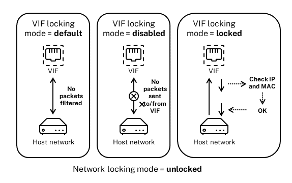
-
Network_default. When the VIF’s state is set to
network_default, XenServer uses the network’sdefault-locking-modeparameter to determine if and how to filter packets traveling through the VIF. The behavior varies according to if the associated network has the network default locking mode parameter set to disabled or unlocked:-
default-locking-mode=disabled, XenServer applies a filtering rule so that the VIF drops all traffic.-
default-locking-mode=unlocked, XenServer removes all the filtering rules associated with the VIF. By default, the default locking mode parameter is set tounlocked.For information about the
default-locking-modeparameter, see Network commands.The default locking mode of the network has no effect on attached VIFs whose locking state is anything other than
network_default.Note:
You cannot change the
default-locking-modeof a network that has active VIFs attached to it. -
Locked. XenServer applies filtering rules so that only traffic sent to/from the specified MAC and IP addresses is allowed to be sent out through the VIF. In this mode, if no IP addresses are specified, the VM cannot send any traffic through that VIF, on that network.
To specify the IP addresses from which the VIF accepts traffic, use the IPv4 or IPv6 IP addresses by using the
ipv4_allowedoripv6_allowedparameters. However, if you have the Linux bridge configured, do not type IPv6 addresses.XenServer lets you type IPv6 addresses when the Linux bridge is active. However, XenServer cannot filter based on the IPv6 addresses typed. The reason is the Linux bridge does not have modules to filter Neighbor Discovery Protocol (NDP) packets. Therefore, complete protection cannot be implemented and guests would be able to impersonate another guest by forging NDP packets. As result, if you specify even one IPv6 address, XenServer lets all IPv6 traffic pass through the VIF. If you do not specify any IPv6 addresses, XenServer does not let any IPv6 traffic pass through to the VIF.
-
Unlocked. All network traffic can pass through the VIF. That is, no filters are applied to any traffic going to or from the VIF.
-
Disabled. No traffic is allowed to pass through the VIF. (That is, XenServer applies a filtering rule so that the VIF drops all traffic.)
Configure switch port locking
This section provides three different procedures:
-
Restrict VIFs to use a specific IP address
-
Add an IP address to an existing restricted list. For example, to add an IP address to a VIF when the VM is running and connected to the network (for example, if you are taking a network offline temporarily).
-
Remove an IP address from an existing restricted list
If a VIF’s locking-mode is set to locked, it can only use the addresses specified in the ipv4-allowed or ipv6-allowed parameters.
Because, in some relatively rare cases, VIFs may have more than one IP address, it is possible to specify multiple IP addresses for a VIF.
You can perform these procedures before or after the VIF is plugged in (or the VM is started).
Change the default-locking mode to locked, if it is not using that mode already, by running the following command:
xe vif-param-set uuid=vif-uuid locking-mode=locked
<!--NeedCopy-->
The vif-uuid represents the UUID of the VIF you want to allow to send traffic. To obtain the UUID, run the xe vif-list command on the host. vm-uuid Indicates the virtual machine for which the information appears. The device ID indicates the device number of the VIF.
Run the vif-param-set command to specify the IP addresses from which the virtual machine can send traffic. Do one or more of the following:
-
Specify one or more IPv4 IP addresses destinations. For example:
xe vif-param-set uuid=vif-uuid ipv4-allowed=comma separated list of ipv4-addresses <!--NeedCopy--> -
Specify one or more IPv6 IP addresses destinations. For example:
 xe vif-param-set uuid=vif-uuid ipv6-allowed=comma separated list of ipv6-addresses
 <!--NeedCopy-->
You can specify multiple IP addresses by separating them with a comma, as shown in the preceding example.
After performing the procedure to restrict a VIF to using a specific IP address, you can add one or more IP addresses the VIF can use.
Run the vif-param-add command to add the IP addresses to the existing list. Do one or more of the following:
-
Specify the IPv4 IP address. For example:
xe vif-param-add uuid=vif-uuid ipv4-allowed=comma separated list of ipv4-addresses <!--NeedCopy--> -
Specify the IPv6 IP address. For example:
 xe vif-param-add uuid=vif-uuid ipv6-allowed=comma separated list of ipv6-addresses
 <!--NeedCopy-->
If you restrict a VIF to use two or more IP addresses, you can delete one of those IP addresses from the list.
Run the vif-param-remove command to delete the IP addresses from the existing list. Do one or more of the following:
-
Specify the IPv4 IP address to delete. For example:
xe vif-param-remove uuid=vif-uuid ipv4-allowed=comma separated list of ipv4-addresses <!--NeedCopy--> -
Specify the IPv6 IP address to delete. For example:
 xe vif-param-remove uuid=vif-uuid ipv6-allowed=comma separated list of ipv6-addresses
 <!--NeedCopy-->
Prevent a virtual machine from sending or receiving traffic from a specific network
The following procedure prevents a virtual machine from communicating through a specific VIF. As a VIF connects to a specific XenServer network, you can use this procedure to prevent a virtual machine from sending or receiving any traffic from a specific network. This provides a more granular level of control than disabling an entire network.
If you use the CLI command, you do not need to unplug the VIF to set the VIF’s locking mode. The command changes the filtering rules while the VIF is running. In this case, the network connection still appears to be present, however, the VIF drops any packets the VM attempts to send.
Tip:
To find the UUID of a VIF, run the xe
vif-listcommand on the host. The device ID indicates the device number of the VIF.
To prevent a VIF from receiving traffic, disable the VIF connected to the network from which you want to stop the VM from receiving traffic:
xe vif-param-set uuid=vif-uuid locking-mode=disabled
<!--NeedCopy-->
You can also disable the VIF in XenCenter by selecting the virtual network interface in the VM’s Networking tab and clicking Deactivate.
Remove a VIF’s restriction to an IP address
To revert to the default (original) locking mode state, use the following procedure. By default, when you create a VIF, XenServer configures it so that it is not restricted to using a specific IP address.
To revert a VIF to an unlocked state, change the VIF default-locking mode to unlocked. If it is not using that mode already, run the following command:
xe vif-param-set uuid=vif_uuid locking-mode=unlocked
<!--NeedCopy-->
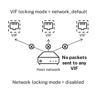
Simplify VIF locking mode configuration in the Cloud
Rather than running the VIF locking mode commands for each VIF, you can ensure all VIFs are disabled by default. To do so, you must change the packet filtering at the network level. Changing the packet filtering causes the XenServer network to determine how packets are filtered, as described in the previous section How switch-port locking works.
Specifically, a network’s default-locking-mode setting determines how new VIFs with default settings behave. Whenever a VIF’s locking-mode is set to default, the VIF refers to the network-locking mode (default-locking-mode) to determine if and how to filter packets traveling through the VIF:
-
Unlocked. When the network
default-locking-modeparameter is set tounlocked, XenServer lets the VM send traffic to any IP address on the network the VIF connects to. -
Disabled. When the
default-locking-modeparameter is set todisabled, XenServer applies a filtering rule so that the VIF drops all traffic.
By default, the default-locking-mode for all networks created in XenCenter and using the CLI are set to unlocked.
By setting the VIF’s locking mode to its default (network_default), you can create a basic default configuration (at the network level) for all newly created VIFs that connect to a specific network.
This illustration shows how, when a VIF’s locking-mode is set to its default setting (network_default), the VIF uses the network default-locking-mode to determine its behavior.
For example, by default, VIFs are created with their locking-mode set to network_default. If you set a network’s default-locking-mode=disabled, any new VIFs for which you have not configured the locking mode are disabled. The VIFs remain disabled until you either (a) change the individual VIF’s locking-mode parameter or (b) explicitly set the VIF’s locking-mode to `unlocked. This is helpful when you trust a specific VM enough so you do not want to filter its traffic at all.
To change a network’s default locking mode setting:
After creating the network, change the default-locking mode by running the following command:
xe network-param-set uuid=network-uuid default-locking-mode=[unlocked|disabled]
<!--NeedCopy-->
Note:
To get the UUID for a network, run the xe
network-listcommand. This command displays the UUIDs for all the networks on the host on which you ran the command.
To check a network’s default locking mode setting:
Run one of the following commands:
xe network-param-get uuid=network-uuid param-name=default-locking-mode
<!--NeedCopy-->
OR
xe network-list uuid=network-uuid params=default-locking-mode
<!--NeedCopy-->
Use network settings for VIF traffic filtering
The following procedure instructs a VIF on a virtual machine to use the XenServer network default-locking-mode settings on the network itself to determine how to filter traffic.
-
Change the VIF locking state to
network_default, if it is not using that mode already, by running the following command:xe vif-param-set uuid=vif_uuid locking-mode=network_default <!--NeedCopy--> -
Change the default-locking mode to
unlocked, if it is not using that mode already, by running the following command:xe network-param-set uuid=network-uuid default-locking-mode=unlocked <!--NeedCopy-->