Integrate Citrix SD-WAN and iboss cloud
Citrix SD-WAN helps enterprises move to the cloud by securely enabling local branch-to-Internet breakouts that can allow or deny Internet access directly from the branch. Citrix SD-WAN identifies applications through a combination of an integrated database of over 4,500 applications, including individual SaaS applications, and uses deep packet inspection technology for real-time discovery and classification of applications. It uses this application knowledge to intelligently steer traffic from the branch to the Internet, cloud or SaaS.
The iboss cloud secures Internet access on any device, from any location, in the cloud. iboss provides in-the-cloud security for branch offices where Internet traffic is offloaded from private office connections via Internet breakouts. Users receive best-of-breed internet protection including compliance, web filtering, SSL inspection, file- and stream-based security, malware defense, and data loss prevention. The traffic is secured in the cloud, with centralized security policies across all branch offices and instant scaling as bandwidth grows.
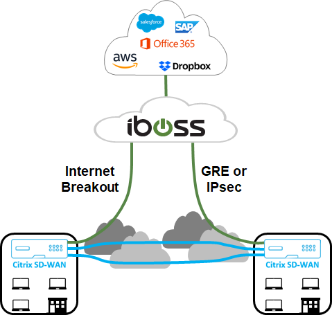
The combination of Citrix SD-WAN and the iboss Cloud enables enterprises to transform their WAN securely. The overall solution architecture is shown in the following figure.
iboss configuration
Login
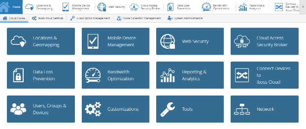
The iboss configuration is provisioned through the iboss dashboard GUI.
To log in to the management interface, using an Internet browser navigate to www.ibosscloud.com.
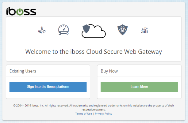
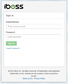
Click Sign into the iboss platform and provide your credentials.
Network subnets
Many customers create policies for SD-WAN deployments based on branch network subnets. It is recommended that you add a blanket subnet for each private range used on your network (for example 10.0.0.0/255.0.0.0) and then create more specific subnets as needed. To create a network subnet, select the Network tile from the Home page.
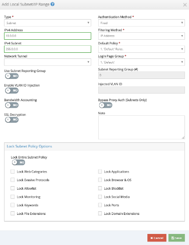
Navigate to Local Subnets > + New Local Subnet/IP Range.

Enter or select values for the required fields and click Save.
Tunnels
After the network subnets are provisioned, either GRE or IPsec tunnels can be used to connect the branch office to the iboss Cloud if necessary. The following steps show how to configure a single tunnel to a single iboss SWG node. The steps can be replicated to provide multiple tunnels from a single branch appliance or to multiple iboss gateway nodes.
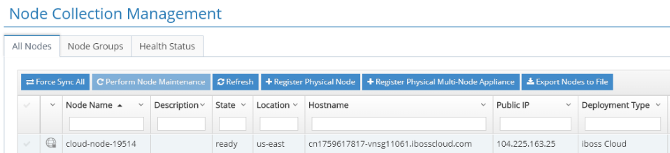
GRE or IPsec tunnels from a Citrix SD-WAN appliance will terminate on the public IP address of an iboss gateway node. To identify the public IP address of an iboss gateway node, return to the Home page, and click Node Collection Management.

Under the All Nodes tab, the Public IP address for a gateway node is the external IP address for the tunnel. In the example below the outside IP of a tunnel on the iboss side would be 104.225.163.25.
GRE
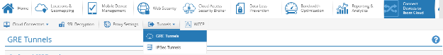
To add a GRE tunnel from a specific location, return to the Home page and click Connect Devices to iboss Cloud.

Click Tunnels and select GRE Tunnels.
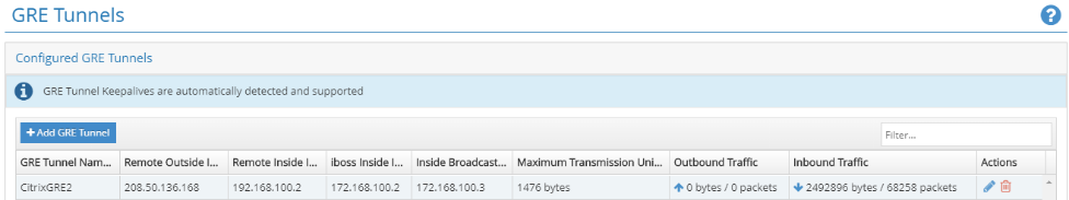
Click +Add GRE Tunnel and enter the required information.
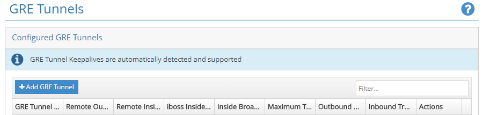
The inside tunnel subnets should be unique for each tunnel (for example 169.254.1.0/30, 169.254.1.4/30, and so on). Unique iboss nodes should be utilized for overlapping subnets between multiple sites. For example, if site ‘A’ and site ‘B’ use the 192.168.1.0/24 subnet, then the GRE tunnel configuration for each of these sites should be performed on different iboss nodes.
Click Save. The tunnel information is presented as a summary. You can edit it if necessary.
IPsec
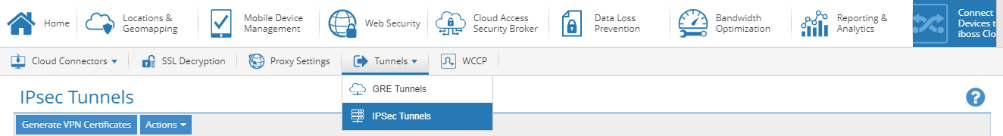
To add an IPsec tunnel from a specific location, return to the Home page and click Connect Devices to iboss Cloud.

Click Tunnels and select IPsec Tunnels.
When connecting tunnels from a Citrix SD-WAN appliance, we recommend the following IPsec Settings that are common across all tunnels:
- IKE Lifetime (minutes): 60
- Key Life (minutes): 20
- Rekey Margin (minutes): 3
- Rekey Attempts: 1
All other settings (for example IPsec Tunnel Secret, and so on) may be deployment specific.
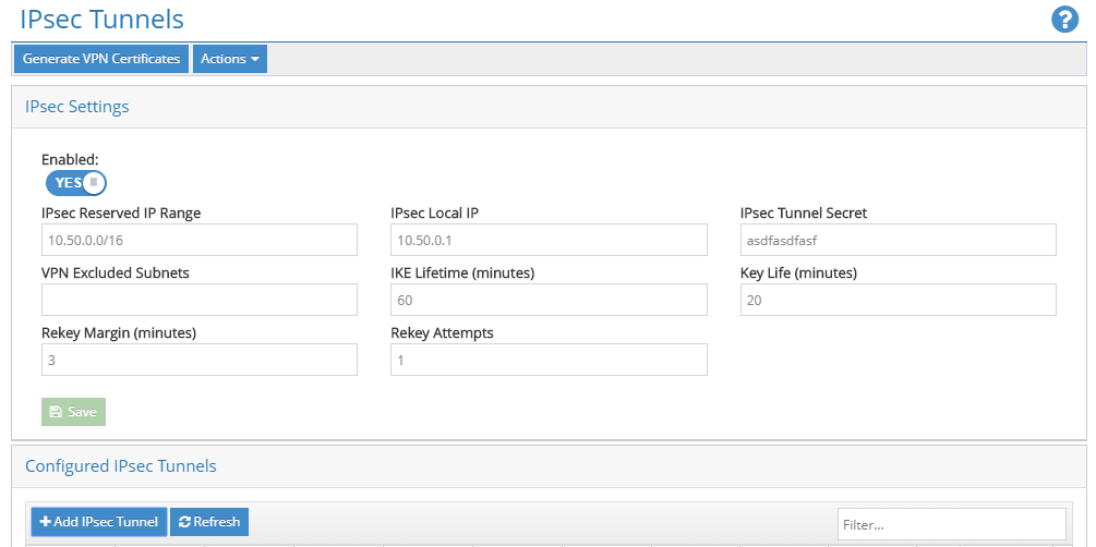
Click + Add IPsec Tunnel to create tunnels as required.
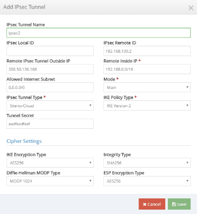
Enter the required information. For an IPsec tunnel from the Citrix SD-WAN appliance, we recommend the following IPsec settings for every tunnel:
- Mode: Main
- IPsec Tunnel Type: Site-to-Cloud
- IKE Policy Type: IKE Version 2
- IKE Encryption Type: AES256
- Integrity Type: SHA256
- Diffie-Hellman MODP Type: MODP 1024
- ESP Encryption Type: AES256
All other settings (for example Remote IPsec Tunnel Outside IP, and so on) may be deployment specific. The inside tunnel subnets should be unique for each tunnel (for example 169.254.1.0/30, 169.254.1.4/30, and so on). Unique iboss nodes should be utilized for overlapping subnets between multiple sites. For example, if site ‘A’ and site ‘B’ both use the 192.168.1.0/24 subnet, then the tunnel configuration for each of these sites should be performed on different iboss nodes.
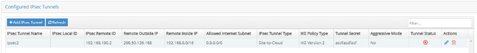
Click Save. The tunnel information is presented as a summary.
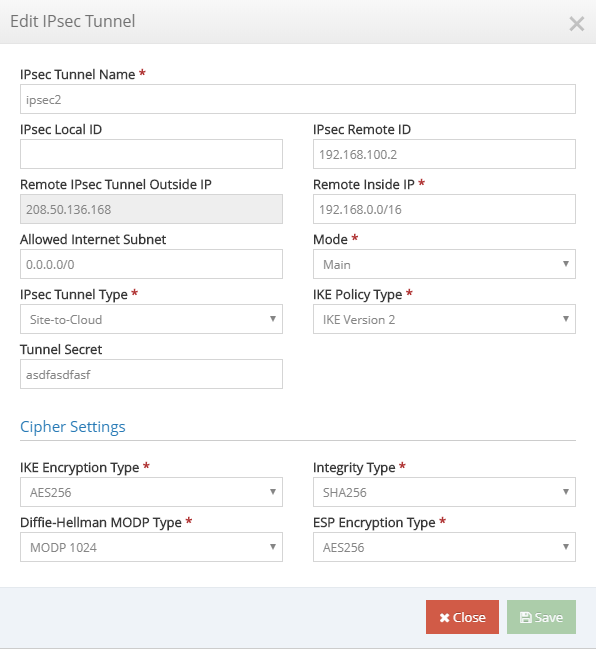
You can edit all the configuration parameters of the tunnel, except Remote IPsec Tunnel Outside IP.
Citrix SD-WAN configuration
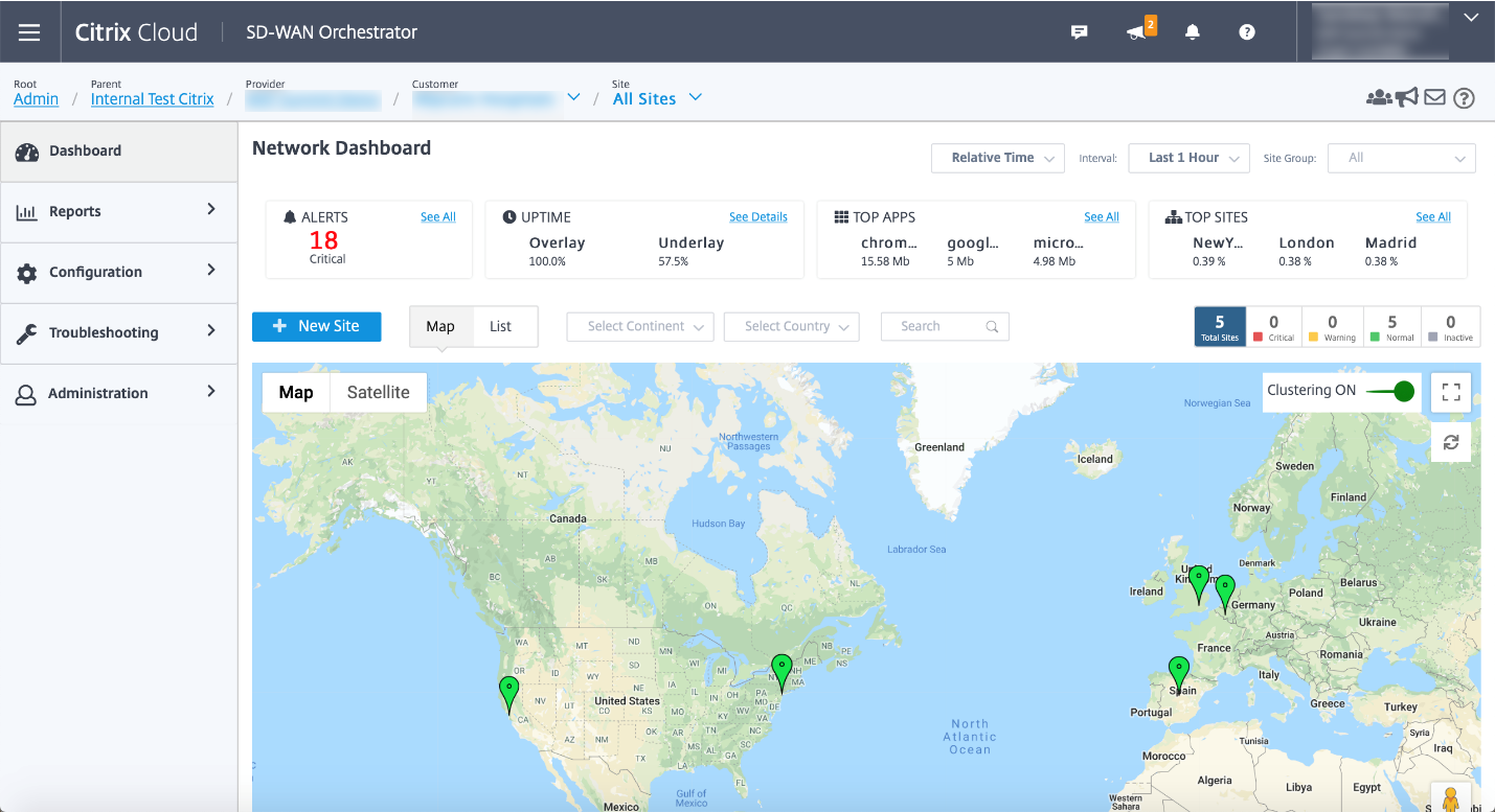
Citrix SD-WAN network is managed through the Citrix Cloud based management service Citrix SD-WAN Orchestrator. If you do not already have an account, see Citrix SD-WAN Orchestrator onboarding.
After successful completing the onboarding process, you can access SD-WAN Orchestrator.
Ensure that the Citrix SD-WAN site is already configured and connected to the branches and networks. For configuration details, see Network configuration.
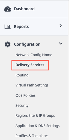
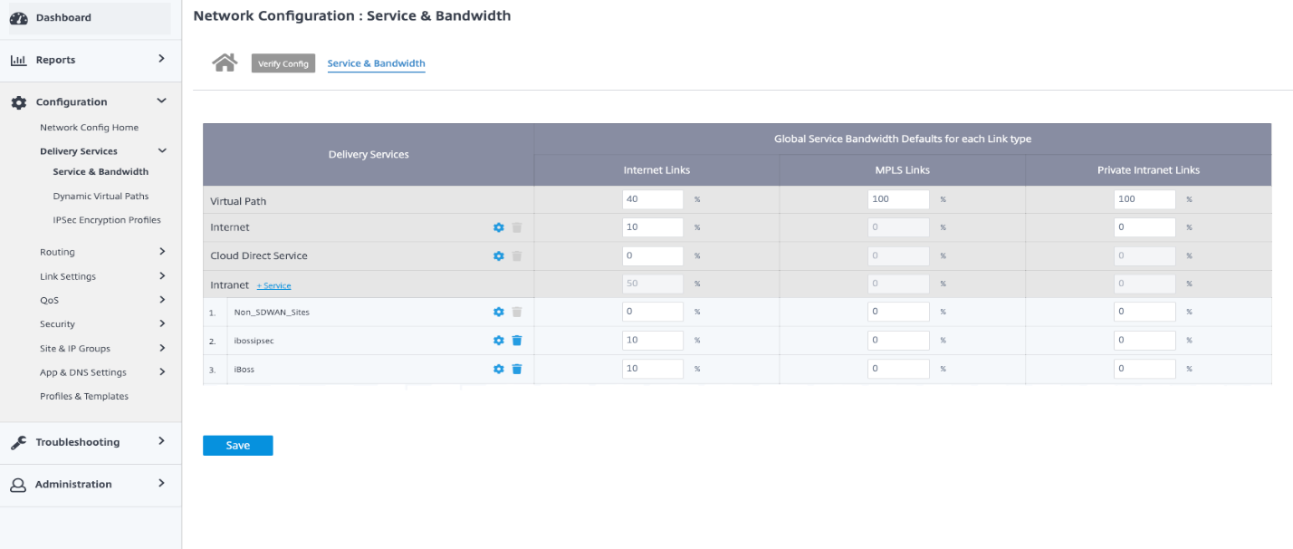
Delivery services
Delivery services allow you to configure delivery services such as the Internet, Intranet, IPsec, and GRE. The delivery services are defined globally and applied to WAN links at individual sites, as applicable.
iboss cloud can be connected from Citrix SD-WAN either through GRE or IPsec services. Please use the settings recommended by iboss in the previous section.
GRE service
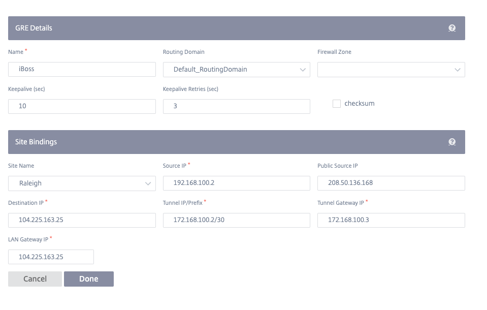
You can configure SD-WAN appliances to terminate GRE tunnels. Configure the following settings.
GRE details:
- Name: The Name of the GRE service.
- Routing Domain: The routing domain for the GRE tunnel.
- Firewall Zone: The firewall zone chosen for the tunnel. By default, the tunnel is placed into the Default_LAN_Zone.
- Keep alive: The period between sending keep alive messages. If configured to 0, no keep alive packets is sent, but the tunnel stays up.
- Keep alive Retries: The number of times that the Citrix SD-WAN appliance sends keep alive packets without a response before it brings the tunnel-down.
- Checksum: Enable or disable checksum for the tunnel’s GRE header.
Site bindings:
- Site Name: The site to map the GRE tunnel.
- Source IP: The source IP address of the tunnel. This is one of the virtual interfaces configured at this site. The selected routing domain determines the available source IP addresses.
- Public Source IP: The source IP if the tunnel traffic is going through NAT.
- Destination IP: The destination IP address of the tunnel.
- Tunnel IP/Prefix: The IP address and prefix of the GRE Tunnel.
- Tunnel Gateway IP: The next hop IP address to route the tunnel traffic.
- LAN Gateway IP: The next hop IP address to route the LAN traffic.
IPsec service
Citrix SD-WAN appliances can negotiate fixed IPsec tunnels with third-party peers on the LAN or WAN side. You can define the tunnel end-points and map sites to the tunnel end-points.
You can also select and apply an IPsec security profile that define the security protocol and IPsec settings.
To add IPsec encryption profile, navigate to Configuration > Delivery Services > select IPsec Encryption Profiles tab.
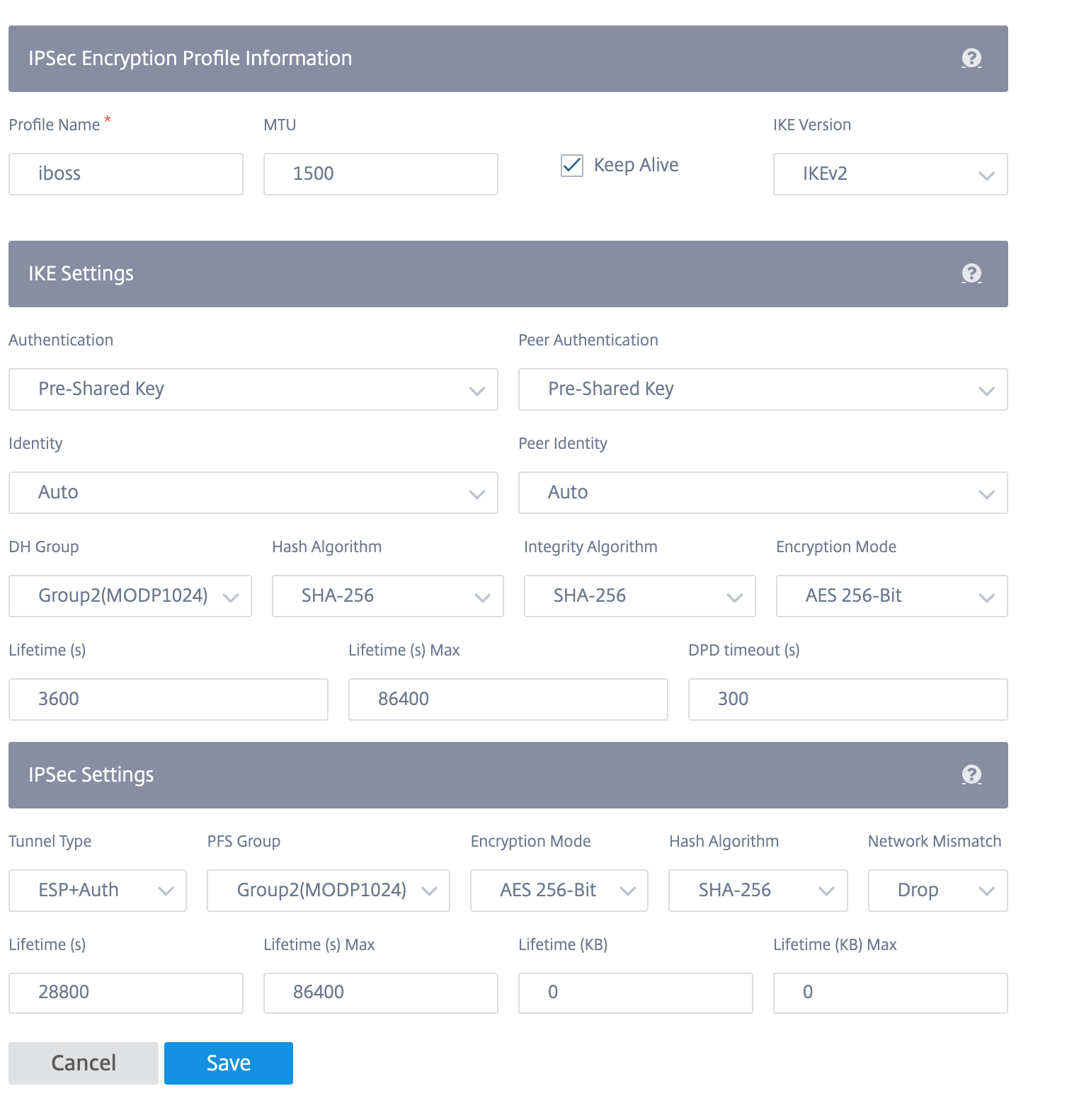
IPsec profiles are used while configuring IPsec services as delivery service sets. In the IPsec security profile page, enter the required values for the IPsec Encryption Profile, IKE Settings, and IPsec Settings.
IPsec encryption profile information:
- Profile Name: The name of the profile.
- MTU: The maximum IKE or IPsec packet size in bytes.
- Keep Alive: Keep the tunnel active and enable route eligibility.
- IKE Version: The IKE protocol version.
IKE settings:
-
Mode: Select either Main mode or Aggressive mode for the IKE Phase 1 negotiation mode.
- Main: No information is exposed to potential attackers during negotiation, but is slower than Aggressive mode.
- Aggressive: Some information (for example, the identity of the negotiating peers) is exposed to potential attackers during negotiation, but is faster than Main mode.
- Authentication: The authentication type, Certificate, or Pre-shared Key.
- Identity: The identity method.
- Peer Identity: The peer identity method.
- DH Group: The Diffie-Hellman (DH) group that are available for IKE key generation.
- Hash Algorithm: The hashing algorithm to authenticate IKE messages.
- Encryption Mode: The Encryption Mode for IKE messages.
- Lifetime (s): The preferred duration (in seconds) for an IKE security association to exist.
- Lifetime (s) Max: The maximum preferred duration (in seconds) to allow an IKE security association to exist.
- DPD timeout (s): The Dead Peer Detection timeout (in seconds) for VPN connections.
IPsec settings:
-
Tunnel Type: The tunnel encapsulation type.
- ESP: Encrypts the user data only.
- ESP+Auth: Encrypts the user data and includes an HMAC.
- ESP+NULL: Packets are authenticated but not encrypted.
- AH: Only includes an HMAC.
- PFS Group: The Diffie–Hellman group to use for perfect forward secrecy key generation.
- Encryption Mode: The Encryption Mode for IPsec messages from the drop-down menu.
- Hash Algorithm: The MD5, SHA1, and SHA-256 hashing algorithms are available for HMAC verification.
- Network Mismatch: The action to take if a packet does not match the IPsec Tunnel’s Protected Networks.
- Lifetime (s): The amount of time (in seconds) for an IPsec security association to exist.
- Lifetime (s) Max: The maximum amount of time (in seconds) to allow an IPsec security association to exist.
- Lifetime (KB): The amount of data (in kilobytes) for an IPsec security association to exist.
- Lifetime (KB) Max: The maximum amount of data (in kilobytes) to allow an IPsec security association to exist.
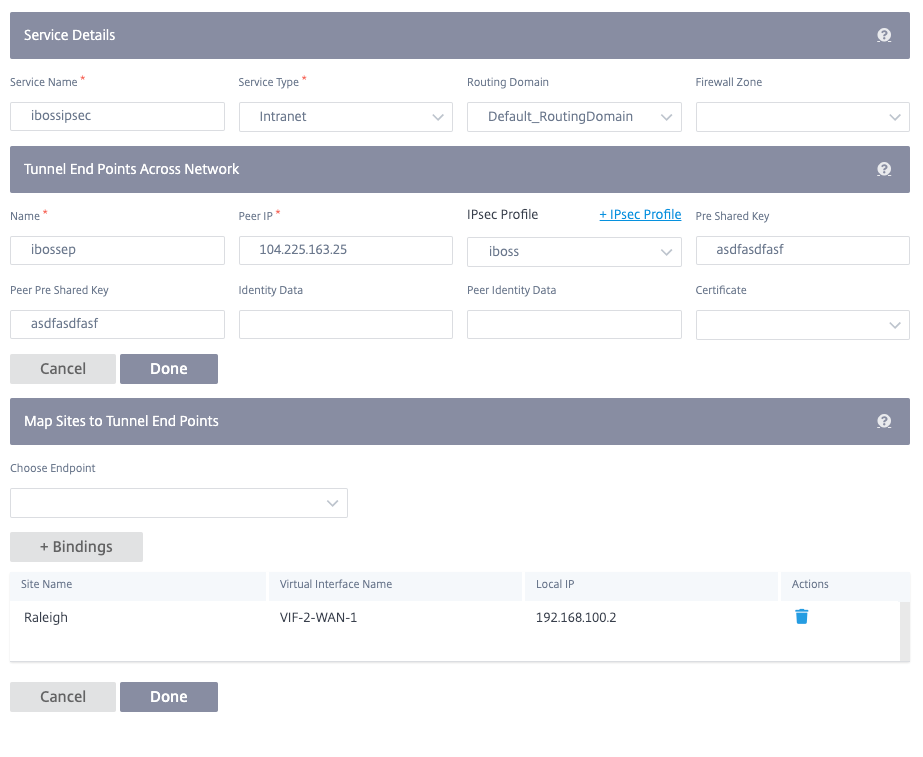
To configure IPsec tunnel:
-
Specify the service details:
- Service Name: The name of the IPsec service.
- Service Type: The service that the IPsec tunnel uses.
- Routing Domain: For IPsec tunnels over LAN, select a routing domain. If the IPsec Tunnel uses an intranet service, the intranet service determines the routing domain.
- Firewall Zone: The firewall zone for the Tunnel. By default, the Tunnel is placed into the Default_LAN_Zone.
-
Add the tunnel end-point.
- Name: When Service Type is Intranet, choose an Intranet Service the tunnel protects. Otherwise, enter a name for the service.
- Peer IP: The IP address of the remote peer.
- IPsec Profile: IPsec security profile that define the security protocol and IPsec settings.
- Pre Shared Key: The pre shared key used for IKE authentication.
- Peer Pre Shared Key: The pre-shared key used for IKEv2 authentication.
- Identity Data: The data to be used as the local identity, when using manual identity or User FQDN type.
- Peer Identity Data: The data to be used as the peer identity, when using manual identity or User FQDN type.
- Certificate: If you choose Certificate as the IKE authentication, choose from the configured certificates.
- Map sites to the tunnel end-points.
- Choose Endpoint: The end-point to be mapped to a site.
- Site Name: The site to be mapped to the end-point.
- Virtual Interface Name: The virtual interface at the site to be used as the end-point.
- Local IP: The local virtual IP address to use as the local tunnel end-point.
-
Create the protected network.
- Source Network IP/Prefix: The source IP address and Prefix of the network traffic that the IPsec tunnel protects.
- Destination Network IP/Prefix: The destination IP address and Prefix of the network traffic that the IPsec tunnel protects.
- Ensure that the IPsec configurations are mirrored on the peer appliance.
IPsec provides secure tunnels. Citrix SD-WAN supports IPsec virtual paths, enabling third-party devices to terminate IPsec VPN Tunnels on the LAN or WAN side of a Citrix SD-WAN appliance. You can secure site-to-site IPsec Tunnels terminating on an SD-WAN appliance by using a 140-2 Level 1 FIPS certified IPsec cryptographic binary.
Citrix SD-WAN also supports resilient IPsec tunneling using a differentiated virtual path tunneling mechanism.
Monitoring GRE and IPSEC tunnels
GRE tunnels
You can use a tunneling mechanism to transport packets of one protocol within another protocol. The protocol that carries the other protocol is called the transport protocol, and the carried protocol is called the passenger protocol. Generic Routing Encapsulation (GRE) is a tunneling mechanism that uses IP as the transport protocol and can carry many different passenger protocols.
The tunnel source address and destination address are used to identify the two endpoints of the virtual point-to-point links in the tunnel.
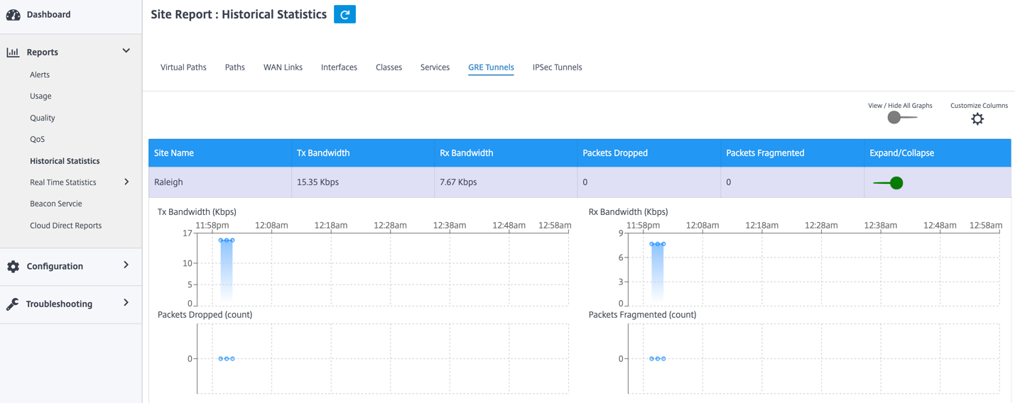
To view GRE Tunnel statistics, navigate to Reports > Statistics > GRE Tunnels. You can view the following metrics:
- Site Name: The site name.
- Tx Bandwidth: Bandwidth transmitted.
- Rx Bandwidth: Bandwidth received.
- Packet Dropped: Number of packets dropped, because of network congestion.
- Packets Fragmented: Number of packets fragmented. Packets are fragmented to create smaller packets that can pass through a link with an MTU that is smaller than the original datagram. The fragments are reassembled by the receiving host.
- Expand/Collapse: You can expand or collapse the data as needed.
IPsec tunnels
IP Security (IPsec) protocols provide security services such as encrypting sensitive data, authentication, protection against replay, and data confidentiality for IP packets. Encapsulating Security Payload (ESP), and Authentication Header (AH) are the two IPsec security protocols used to provide these security services.
In IPsec tunnel mode, the entire original IP packet is protected by IPsec. The original IP packet is wrapped and encrypted, and a new IP header is added before transmitting the packet through the VPN tunnel.
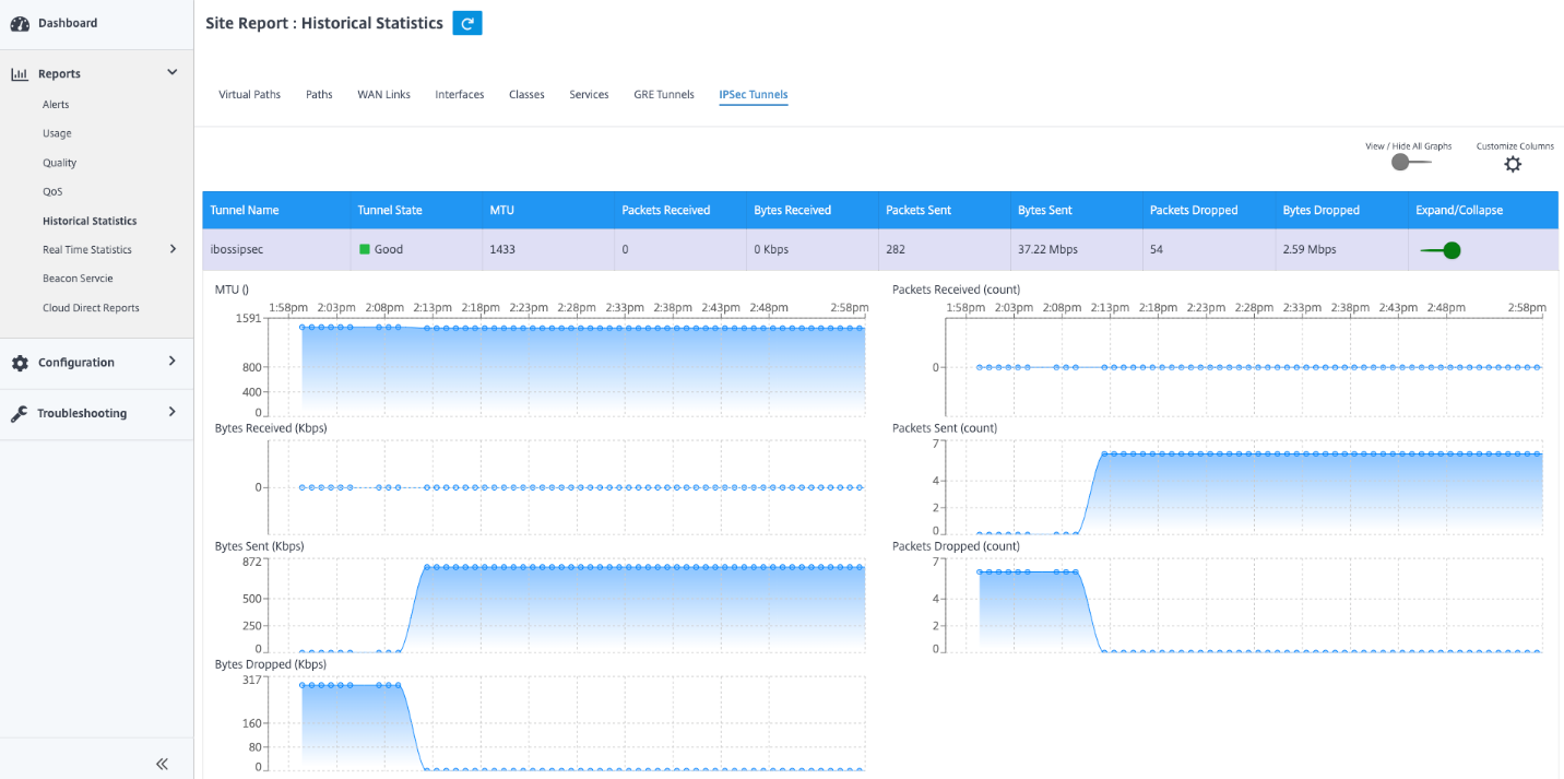
To view IPsec Tunnel statistics, navigate to Reporting > Statistics > IPsec Tunnels.
You can view the following metrics:
- Tunnel Name: The tunnel name.
- Tunnel State: IPsec tunnel state.
- MTU: Maximum transmission unit—size of the largest IP datagram that can be transferred through a specific link.
- Packet Received: Number of packets received.
- Packets Sent: Number of packets Sent.
- Packet Dropped: Number of packets dropped, because of network congestion.
- Bytes Dropped: Number of bytes dropped.
- Expand/Collapse: You can expand or collapse the data as needed.